Propeller shaft for vehicle

a technology for propeller shafts and vehicles, applied in mechanical devices, couplings, transportation and packaging, etc., can solve the problems of insufficient axial variation of the length of the propeller shaft in an axial direction, insufficient impact energy absorbed, and passenger injury degree increasing

Active Publication Date: 2016-04-05
HYUNDAI MOTOR CO LTD +2
View PDF20 Cites 11 Cited by
  • Summary
  • Abstract
  • Description
  • Claims
  • Application Information

AI Technical Summary

Benefits of technology

[0017]Various aspects of the present invention provide for a propeller shaft for a vehicle including: a shaft wherein along an outer peripheral surface of a section of which a plurality of catching protrusions is formed for a spline-connection; a tube wherein along an inner peripheral surface of which a plurality of catching grooves to be meshed with a plurality of catching protrusions is formed for a spline-connection; a stopper member which is provided to be fixed to an inner peripheral surface of the tube, one end of which is corresponded to a remote end of the shaft and which is fractured when a collision load is applied thereto; and a locking member one end of which is in contact with one end of the stopper member and which is connected to the shaft and supports both ends of the stopper member together with the shaft thereby restricting a sliding of the shaft, and which is slid inside the tube together with the shaft when the stopper member is fractured.

Problems solved by technology

However, the length variation of a conventional propeller shaft 10 in an axial direction is not sufficient due to high collapse load when a vehicle collision occurs, and as a result the impact caused by the collision is not sufficiently absorbed, thereby increasing the injury degree of a passenger.
However, since the diameter difference between the small diameter portion 13b and the large diameter portion 13c is not great in the conventional propeller shaft 10, the rear movement amount of the small diameter portion 13b is small and thus the length variation of the propeller shaft in an axial direction is not sufficient due to a high collapse load and the impact energy is not absorbed sufficiently, thereby increasing specially the injury degree of a passenger due to a great deceleration of a vehicle.

Method used


Image

  • Propeller shaft for vehicle
  • Propeller shaft for vehicle
  • Propeller shaft for vehicle

Examples


Embodiment Construction

[0041]Reference will now be made in detail to various embodiments of the present invention(s), examples of which are illustrated in the accompanying drawings and described below. While the invention(s) will be described in conjunction with exemplary embodiments, it will be understood that present description is not intended to limit the invention(s) to those exemplary embodiments. On the contrary, the invention(s) is / are intended to cover not only the exemplary embodiments, but also various alternatives, modifications, equivalents and other embodiments, which may be included within the spirit and scope of the invention as defined by the appended claims.

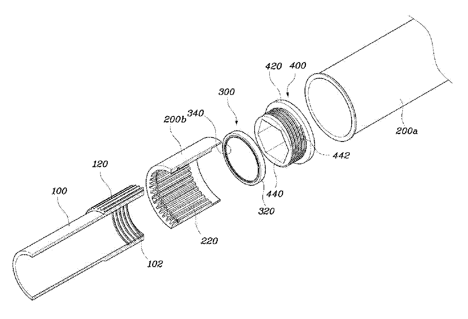
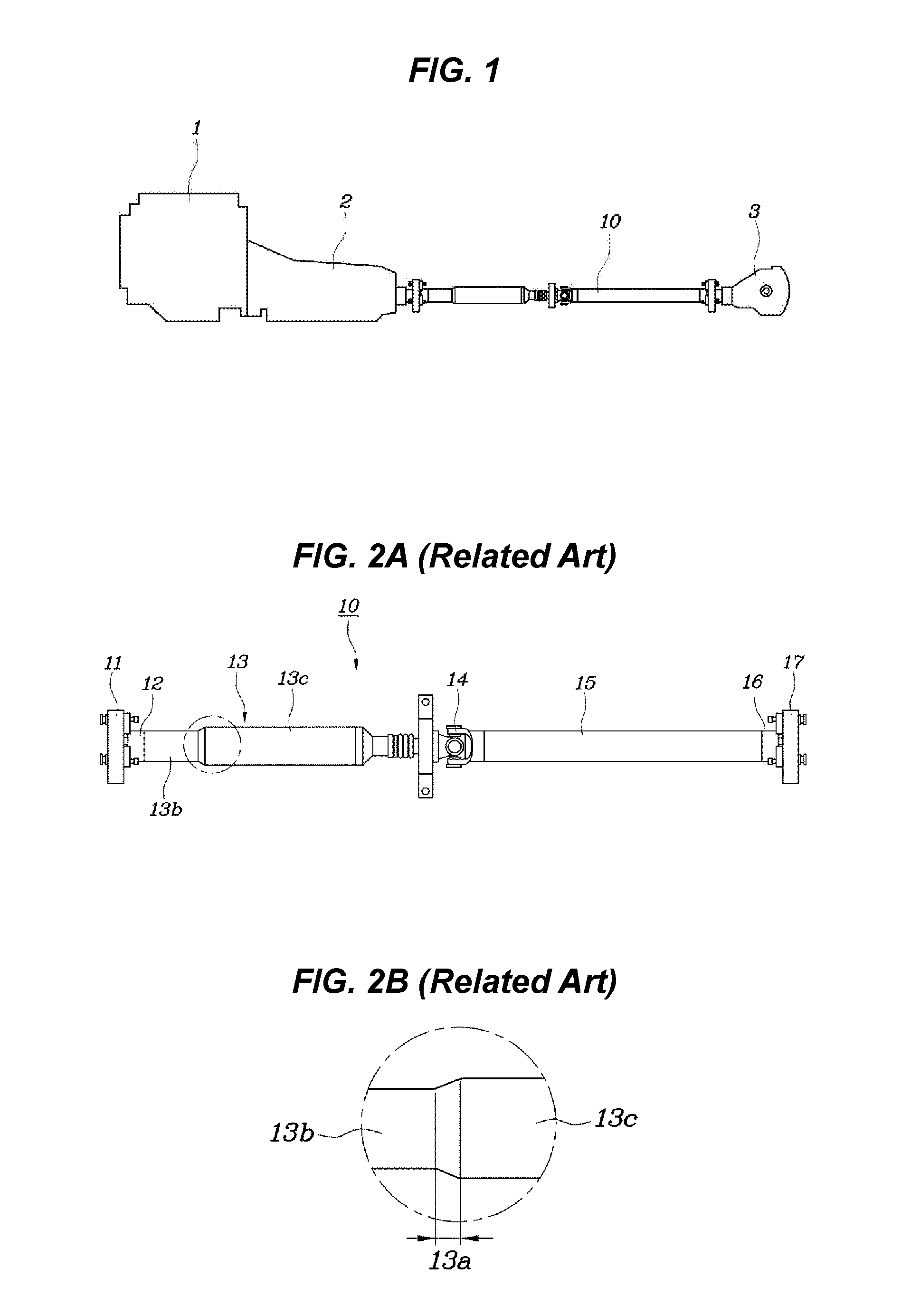
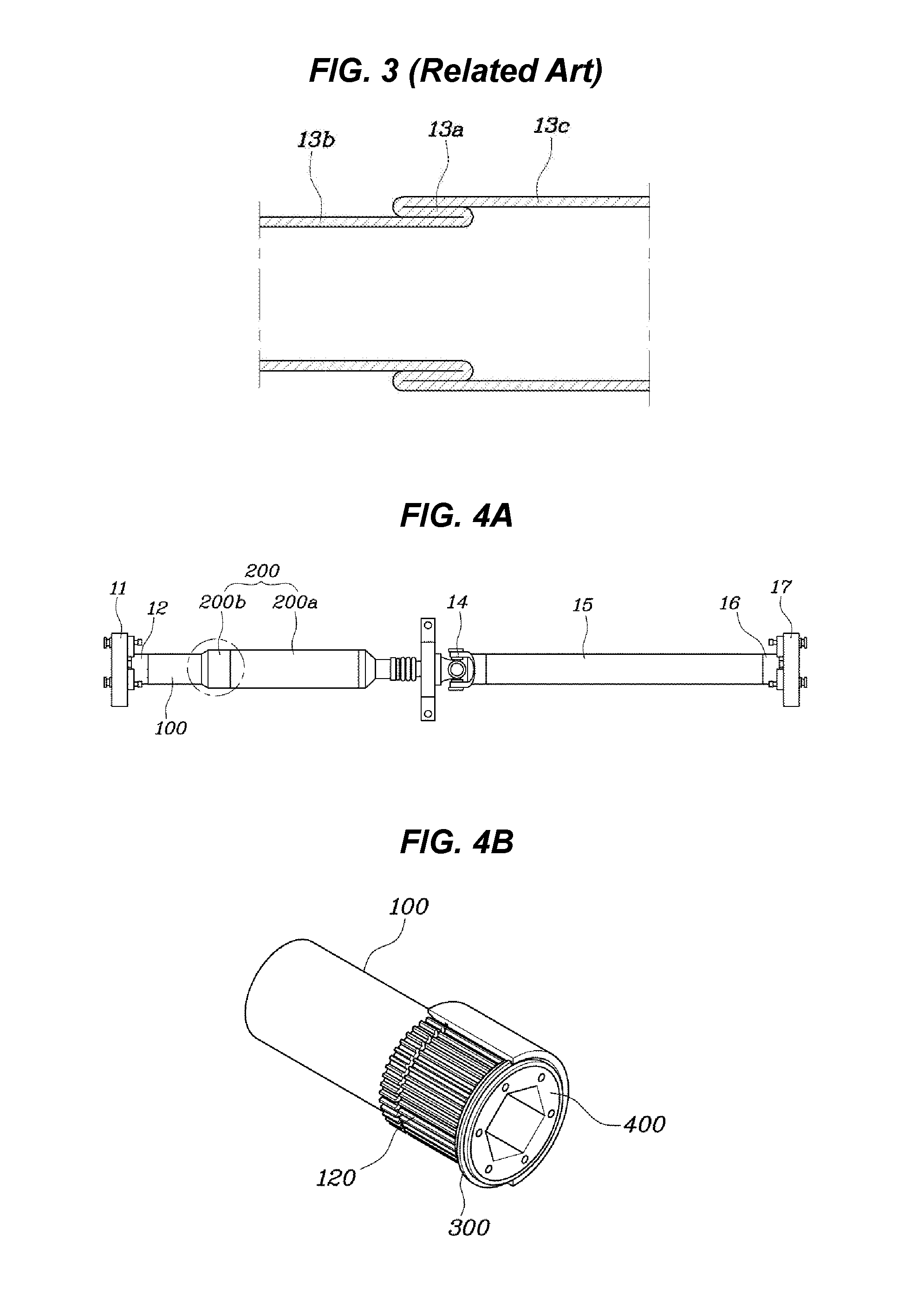
[0042]A propeller shaft for a vehicle according to the present invention, as shown in FIGS. 4 to 9, includes: a front coupling 11 to be connected to a transmission (2; see FIG. 1); a front yoke 12 connected to the front coupling 11; a shaft 100 one end of which is welded to the front yoke 12; a tube 200 that is spline-connected to the...


PUM


Abstract

A propeller shaft for a vehicle includes: a shaft having a plurality of catching protrusions for a spline-connection along an outer peripheral surface; a tube having a plurality of catching grooves along an inner peripheral surface into which the shaft is inserted; a stopper member provided to be fixed to an inner peripheral surface of the tube, one end corresponding to a remote end of the shaft and which is fractured when a collision load is applied thereto; and a locking member one end of which is in contact with one end of the stopper member and which is connected to the shaft and supports both ends of the stopper member together with the shaft, thereby restricting a sliding of the shaft, and which is slid inside the tube together with the shaft when the stopper member is fractured.

Description

CROSS-REFERENCE TO RELATED APPLICATION[0001]The present application claims priority of Korean Patent Application Number 10-2013-0123955 filed Oct. 17, 2013, the entire contents of which application is incorporated herein for all purposes by this reference.BACKGROUND OF INVENTION[0002]1. Field of Invention[0003]The present invention relates to a propeller shaft for a vehicle, and more particularly, to a propeller shaft for a vehicle, capable of absorbing sufficiently length variation of the shaft to an axial direction with a low collapse load when a vehicle collision occurs and thus absorbing sufficiently collision energy, thereby reducing an injury degree of a passenger at a minimum level.[0004]2. Description of Related Art[0005]Generally, a propeller shaft 10 provided in a rear-wheel drive vehicle refers to a power transmission device for transferring smoothly a driving force of a power train constituting of an engine 1 and a transmission 2 to a rear axle 3, as shown in FIG. 1, whe...

Claims


Application Information

Patent Timeline
Patent Type & Authority Patents(United States)
IPC IPC(8): B62D1/19F16C3/02F16D9/06F16D9/08
CPCF16D9/06B62D1/192F16C3/02F16D9/08F16D1/033F16D1/068F16D1/116F16D2001/103F16C3/023B60K17/22
Inventor CHOI, WON JUNYE, BYOUNG WOOKIM, TAE YOULKANG, MOON MO
Owner HYUNDAI MOTOR CO LTD
Why Eureka
Try Eureka