
Foldable supporting stand with positioning means

a technology of positioning means and folding support, which is applied in the direction of machine supports, furniture parts, other domestic objects, etc., can solve the problems of increased probability of damage to the panel display b>4/b> during its transportation, inconvenient use, etc., and achieve the effect of reducing the volume of the package and being easily folded by the user

Inactive Publication Date: 2010-08-17
SYNCMOLD ENTERPRISE CORP
View PDF8 Cites 8 Cited by
  • Summary
  • Abstract
  • Description
  • Claims
  • Application Information

AI Technical Summary

Benefits of technology

[0011]The object of the present invention is to provide a foldable supporting stand with positioning means. The supporting stand can be folded by a user easily, thereby reducing its volume for package.
[0012]The other object of the present invention is to provide a foldable supporting stand with positioning means. With its own weight driving an internal structure of the supporting stand to fix a screen on the supporting stand, the screen can be avoided from moving to suffer damage, thereby reducing the probability of damaging the screen.
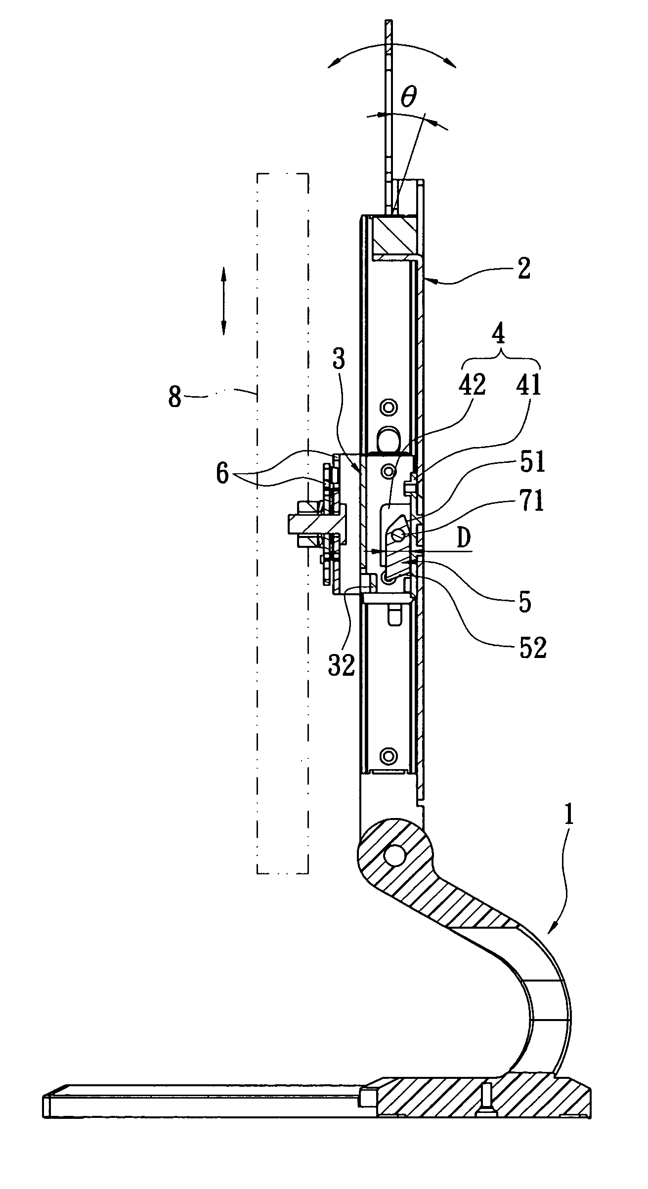
[0013]In order to achieve the above objects, the present invention provides a foldable supporting stand with positioning means, which includes a base, a support rotatably pivoted to the base; a sliding body slidably provided on the support, the sliding body having a stopping portion; a positioning means located between the sliding body and the support, the positioning means being fixedly joined in the support; and a swinging piece swingably connected to the positioning means, wherein the swinging piece selectively locks the stopping portion, thereby restricting the sliding body form sliding.

Problems solved by technology

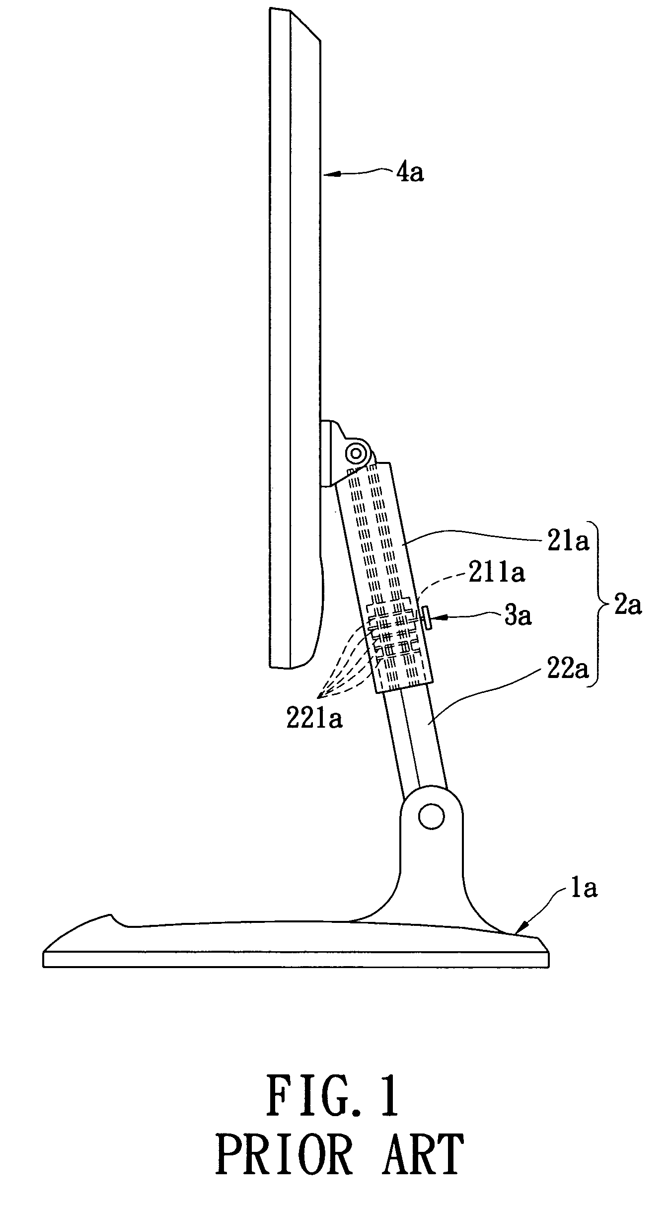
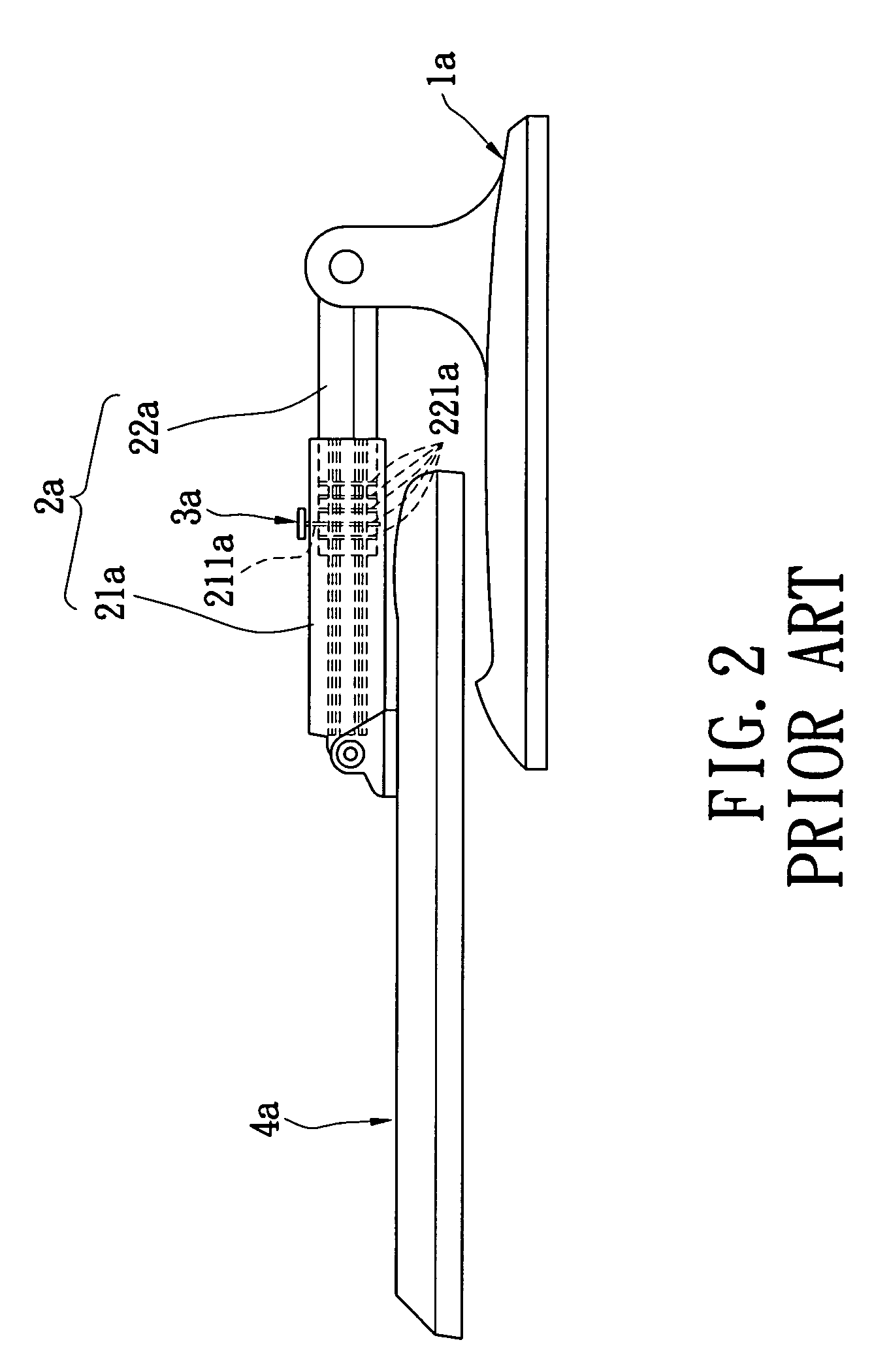
As a result, not only the package volume is increased, but also the probability of damaging the panel display 4a during its transportation is increased.
Thus, it is very inconvenient in use.
Therefore, the first connecting portion 21a may shake and swing when moving due to the gap, so that it may suffer damage after using for a period of time.

Method used


Image

  • Foldable supporting stand with positioning means
  • Foldable supporting stand with positioning means
  • Foldable supporting stand with positioning means

Examples


Embodiment Construction

[0032]Please refer to FIG. 3. The present invention provides a foldable supporting stand with positioning means, which includes a base 1, a support 2, a sliding body 3, a positioning means 4, and a swinging piece 5 (FIGS. 4A and 4B). One end of the support 2 can be rotatably pivoted to the base 1, so that it can be balanced by the base 1 firmly. The sliding body 3 is slidably provided on the support 2, so that the user can move the sliding body 3 arbitrarily according to practical demands. The positioning means 4 is fixed in the support 2. The swinging piece 5 is swingably connected on the positioning means 4. The positioning means 4 and the swinging piece 5 are located between the support 2 and the sliding body 3.

[0033]The support 2 has two bent plates 21 and two grooves 22. The two bent plates 21 extend from left and right sides of the support 2 respectively, and the two bent plates 21 form the two grooves 22.

[0034]The sliding body 3 is provided with at least two sliding blocks 31...


PUM


Abstract

A foldable supporting stand with a positioning mechanism includes a base, a support, a sliding body, a positioning mechanism, and a swinging piece. The support is roatably pivoted to the base. The sliding body is slidably provided on the support and is further connected to a screen. The swinging piece is swingably connected to the positioning mechanism. The positioning mechanism is fixed in the support. When the support is folded in the base, the swinging piece swings toward the sliding body due to its own weight, and is then locked with the sliding body. The locked sliding body is restricted from sliding on the support, so that the screen is thus kept stationary. By that arrangement, the supporting stand has a reduced volume for efficient packaging and storage. Furthermore, the screen is held stationary when being transported.

Description

BACKGROUND OF THE INVENTION[0001]1. Field of the Invention[0002]The present invention relates to a supporting device, and in particular to a foldable supporting stand having a positioning means; wherein by virtue of its design, when a user folds the supporting stand, the positioning means within the supporting stand can be locked with each other via its own weight, thereby fixing a screen connected on the supporting stand.[0003]2. Description of Related Art[0004]The current panel display is usually oriented upright via a supporting stand, so that a user can view the panel display conveniently. Since the supporting stand can be lifted up or lowered, the user can adjust the height of the panel display according to practical demands. Please refer to FIG. 1, which shows a liftable supporting stand assembly for a display. The supporting stand assembly for the display includes a base 1a, a supporting stand 2a connected to the base 1a, and a positioning element 3a. The supporting stand 2a ...

Claims


Application Information

Patent Timeline
Patent Type & Authority Patents(United States)
IPC IPC(8): F16M11/00
CPCF16M11/26F16M11/2021F16M11/28F16M2200/027Y10S248/917
Inventor HU, CHUNG-CHENG
Owner SYNCMOLD ENTERPRISE CORP
Learn More