Rack guide mechanism

a technology of guide mechanism and rack shaft, which is applied in the direction of mechanical equipment, transportation and packaging, hoisting equipment, etc., can solve the problems of increasing the resistance of the rack shaft, affecting the assembly work of the rack guide mechanism, and affecting the stability of the cylindrical portion, so as to prevent the cylindrical portion from being twisted and sliding resistan

Inactive Publication Date: 2016-08-04
SHOWA CORP
View PDF7 Cites 8 Cited by
  • Summary
  • Abstract
  • Description
  • Claims
  • Application Information

AI Technical Summary

Benefits of technology

[0019]With this configuration of the rack guide mechanism, the liquid body is interposed between the inner peripheral surface of the housing hole and the outer peripheral surface of the cylindrical portion, therefore, the sliding resistance between them can be reduced and it is possible to prevent the cylindrical portion from being twisted when housed in the housing hole.
[0020]According to the rack guide mechanism discussed above, both the securement of good steering feeling in the normal state and the smooth restoration of engagement between the pinion shaft and the rack shaft in an emergency can be realized by the single elastic member, therefore, the assembly property of the rack guide mechanism can be improved without the increase in the number of parts.

Problems solved by technology

However, as the force of pressing and biasing the rack guide to the rack shaft is constantly strong in this method, there is a problem that the sliding resistance of the rack shaft is increased and the steering feeling is liable to be deteriorated.
However, the number of parts is increased in the structure of using the disc spring 56 in addition to the compression coil spring 55, which arises a problem that an assembly work of the rack guide mechanism is complicated.
Moreover, as a height dimension of the disc spring 56 is small, a stroke of a compression amount of the disc spring 56, namely, an adjustment stroke of a screwing amount of the screw 54 becomes small, which arises a problem that it is difficult to perform the initial setting of the compression amount of the disc spring 56.

Method used


Image

  • Rack guide mechanism
  • Rack guide mechanism
  • Rack guide mechanism

Examples


Embodiment Construction

[0025]An embodiment of the present invention will be explained with reference to the drawings. The embodiment will be explained by citing an example in which a rack guide mechanism of the present invention is applied to a motor-driven power steering apparatus, however, the present invention is not limited to this and may be applied to a hydraulic power steering apparatus and a manual steering apparatus.

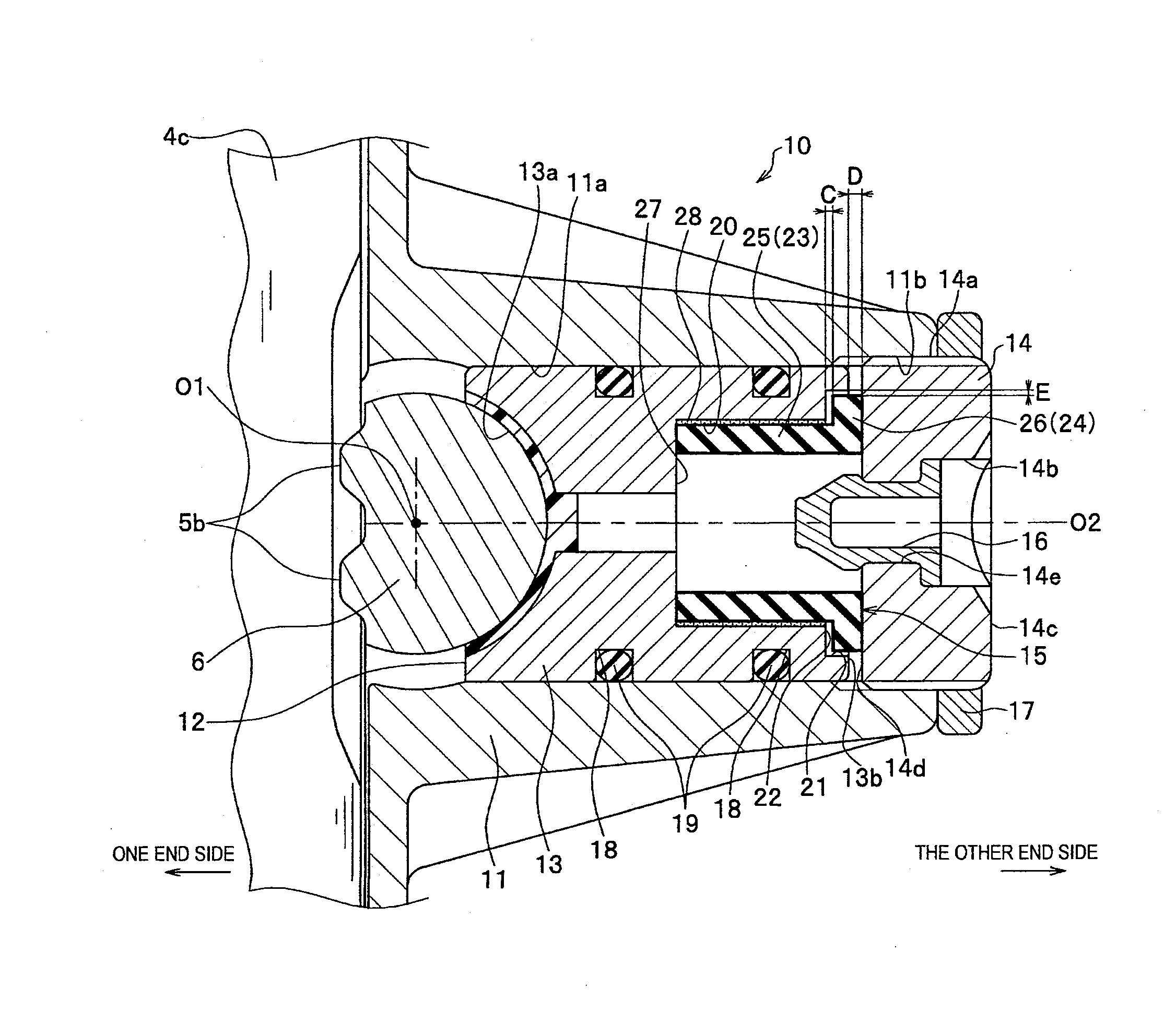
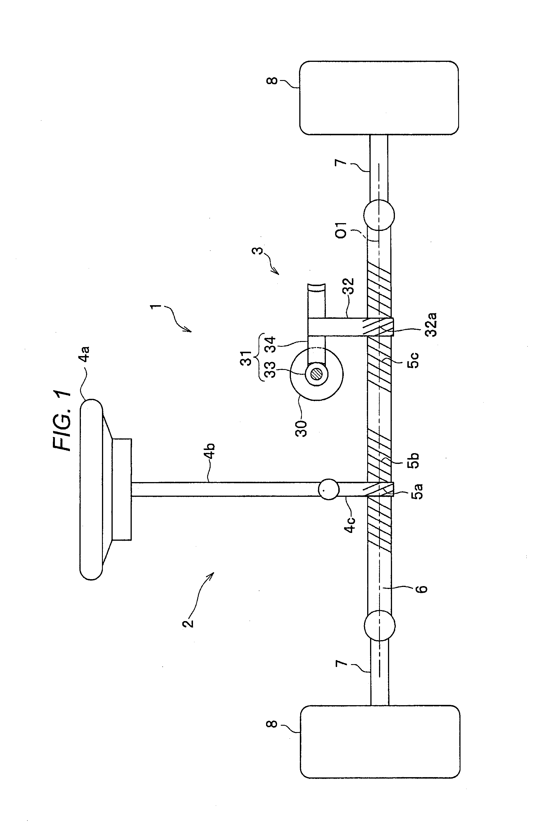
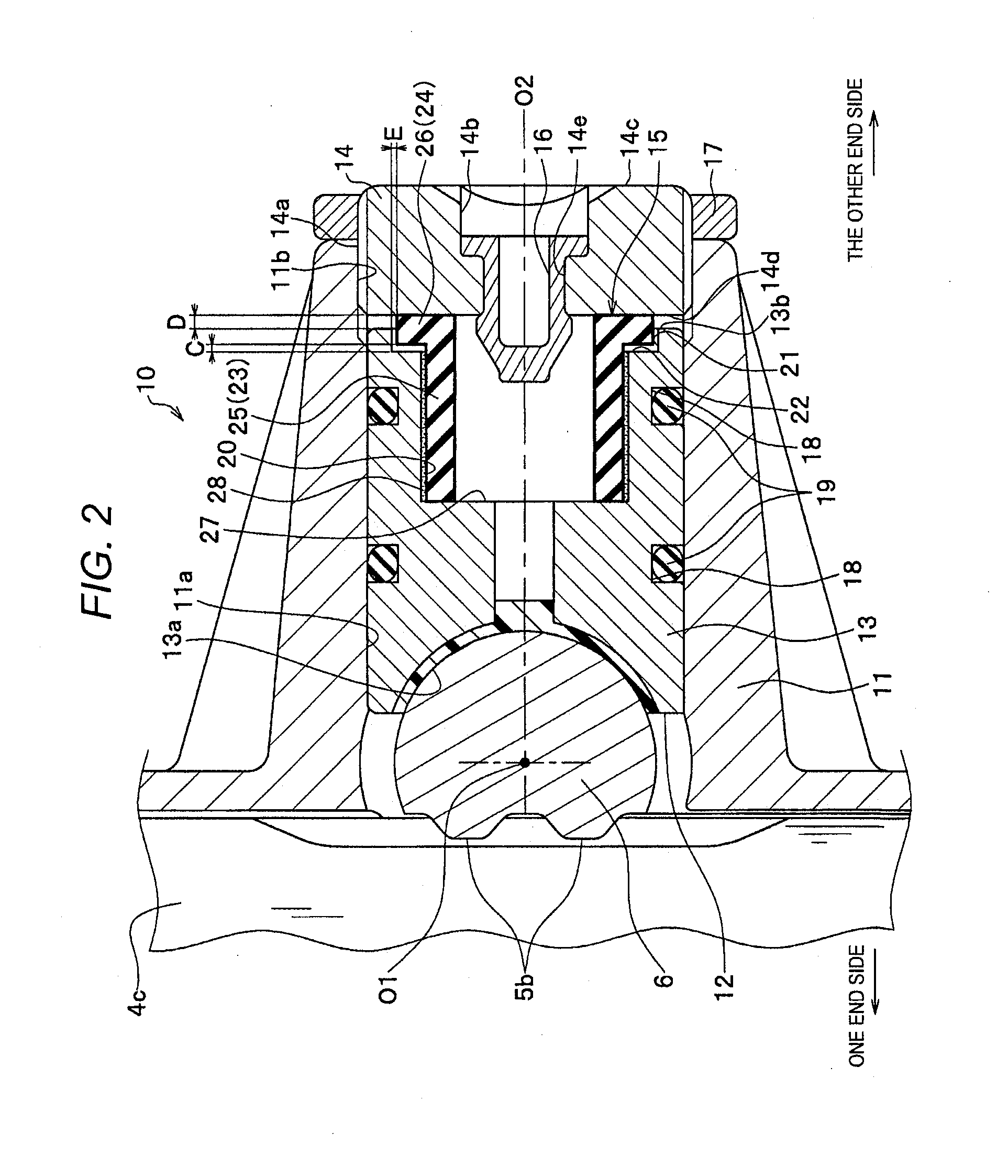
[0026]As shown in FIG. 1, a motor-driven power steering apparatus 1 is a rack and assist type apparatus including a steering mechanism 2 having a rack shaft 6 in which two rack gears which are a rack gear (steering wheel side) 5b and a rack gear (assist side) 5c are formed along a shaft center O1 and an auxiliary torque mechanism 3 giving an auxiliary steering force to the rack shaft 6.

[0027]The steering mechanism 2 includes a steering wheel 4a operated by a driver, a steering shaft 4b rotating by the operation of the steering wheel 4a, a pinion shaft 4c provided on a lower side of th...


PUM


Abstract

A rack guide mechanism includes: a housing; a rack guide housed in the housing so as to move freely, supporting a rack shaft; a lid member attached to the housing; and an elastic member interposed between the rack guide and the lid member, biasing the rack guide to the rack shaft, in which the elastic member includes a first elastic portion constantly sandwiched between the rack guide and the lid member, and a second elastic portion sandwiched between the rack guide and the lid member when the rack guide moves to the lid member side by a given distance, and the first elastic portion and the second elastic portion are integrally formed.

Description

CROSS-REFERENCE TO RELATED APPLICATIONS[0001]This application is based on and claims priority under 35 USC 119 from Japanese Patent Application No. 2015-016911 filed on Jan. 30, 2015, the entire content of which is incorporated herein by reference.BACKGROUND[0002]1. Technical Field[0003]The present invention relates to a rack guide mechanism.[0004]2. Related Art[0005]There is a rack and pinion type steering apparatus which includes a housing, a pinion shaft provided with a pinion gear, to which an operation force of a steering wheel is transmitted, a rack shaft provided with a rack gear engaged with the pinion gear and a rack guide mechanism guiding a moving direction of the rack shaft and biasing the rack shaft to the pinion shaft by an elastic restoring force (for example, refer to JP-A-2002-370654 (Patent Literature 1)).[0006]The rack guide mechanism includes a rack guide provided to the housing so as to slide, a screw (lid member) screwed to the housing, and a compression coil s...

Claims


Application Information

Patent Timeline
Patent Type & Authority Applications(United States)
IPC IPC(8): F16H55/28B62D3/12
CPCB62D3/123F16H55/283
Inventor IMAMURA, ATSUSHI
Owner SHOWA CORP
Why Eureka
Try Eureka