Multi-directional input apparatus

a multi-directional input and input technology, applied in the direction of instruments, pulse techniques, mechanical control devices, etc., can solve the problems of difficult assembly of these movable members, degrading the operational feel, and difficult sliding resistance between the sliding members and the respective receiving surfaces, so as to reduce prevent rattling, and reduce the effect of the overall size of the apparatus

Active Publication Date: 2013-03-19
ALPS ALPINE CO LTD
View PDF12 Cites 9 Cited by
  • Summary
  • Abstract
  • Description
  • Claims
  • Application Information

AI Technical Summary

Benefits of technology

[0009]In light of the above-described situation, the present invention provides a multi-directional input apparatus in which a sliding resistance generated when a shaft portion of an operating member is tilted does not vary in accordance with a tilting direction and which facilitates size reduction and assembly of the multi-directional input apparatus.
[0011]In the multi-directional input apparatus having the above-described structure, the rubbing portion of the sliding member externally fitted to the shaft portion and biased by the elastic member is in elastic contact with the receiving portion of the restraining member. One or both of the rubbing portion and the receiving portion extend along an aspherical surface centered on the tilting center of the shaft portion of the operating member. Therefore, irrespective of the direction in which the shaft portion is tilted, the sliding member can smoothly slide along the receiving portion. As a result, rattling can be prevented and the sliding resistance between the rubbing portion and the receiving portion can be prevented from varying in accordance with the tilting direction. In addition, in the multi-directional input apparatus, rattling which may occur when the shaft portion of the operating member is tilted can be prevented irrespective of the tilting direction simply by placing a single sliding member between the elastic member held by the operating member and the receiving portion of the restraining member. Therefore, the overall size of the apparatus can be reduced and the apparatus can be easily assembled.
[0012]In the above-described structure, the elastic member may include a coil spring, and the coil spring may be disposed between a flange provided on the shaft portion and a spring receiver provided at a second side (side opposite to the rubbing portion) of the sliding member. In such a case, when the shaft portion is tilted, the rubbing portion of the sliding member can be elastically biased against the receiving portion with a stable urging force. Therefore, a desired sliding resistance can be generated between the rubbing portion and the receiving portion. In addition, since the coil spring can be easily fitted to the shaft portion of the operating member, the apparatus can be easily assembled.
[0014]In the multi-directional input apparatus having the above-described structure, the compression coil spring held by the flange of the operating member elastically biases the sliding member which is externally fitted to the shaft portion, so that the rubbing surface of the sliding member is in elastic contact with the receiving portion of the restraining member. In addition, the rubbing surface of the sliding member extends along a convex spherical surface centered on the tilting center of the shaft portion of the operating member. Therefore, irrespective of the direction in which the shaft portion is tilted, the sliding member can smoothly slide along the receiving portion. As a result, rattling can be prevented and the sliding resistance between the rubbing surface and the receiving portion can be prevented from varying in accordance with the tilting direction. In addition, since the compression coil spring, which is wound along a tapered surface, is disposed in a storage space provided at the second side (side opposite to the side at which the rubbing surface is formed) of the sliding member, the overall size of the apparatus can be reduced.
[0015]In the above-described structure, preferably, the supporting means includes a drive member which supports the operating member with a first rotating shaft and a base which supports the drive member with a second rotating shaft, an axial direction of the second rotating shaft being perpendicular to an axial direction of the first rotating shaft. In addition, preferably, the restraining member is attached to the base. In such a case, the operating member can be supported such that the shaft portion thereof is tiltable in multiple directions with a simple structure. In addition, the restraining member can be attached to the base after the compression coil spring and the sliding member are externally fitted to the shaft portion of the operating member attached to the base. Thus, the apparatus can be easily assembled.
[0016]In such a case, preferably, the apparatus further includes a housing which is configured to house the base and which includes a top lid portion with an upper opening which faces the opening in the restraining member and through which the shaft portion of the operating member extends, and the restraining member is held between the top lid portion of the housing and the base. In this case, the restraining member can be easily fixed to the base without using attachment screws or the like. Therefore, the multi-directional input apparatus can be more easily assembled. In this case, preferably, the restraining member is provided with a pair of positioning projections inserted in a pair of positioning holes formed in the base. Accordingly, the restraining member can be extremely easily positioned and attached to the base.

Problems solved by technology

Accordingly, it is difficult to set sliding resistances between the sliding members and the respective receiving surfaces equal to each other.
Thus, the sliding resistances vary in accordance with the tilting direction of the shaft portion, which degrades the operational feel.
Therefore, the process of assembling these movable members is not easy, and it is difficult to reduce the size of the apparatus.

Method used


Image

  • Multi-directional input apparatus
  • Multi-directional input apparatus
  • Multi-directional input apparatus

Examples


first embodiment

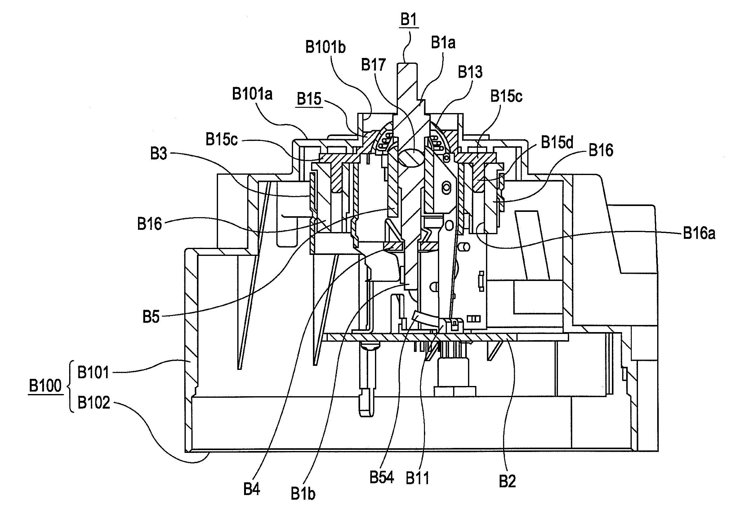
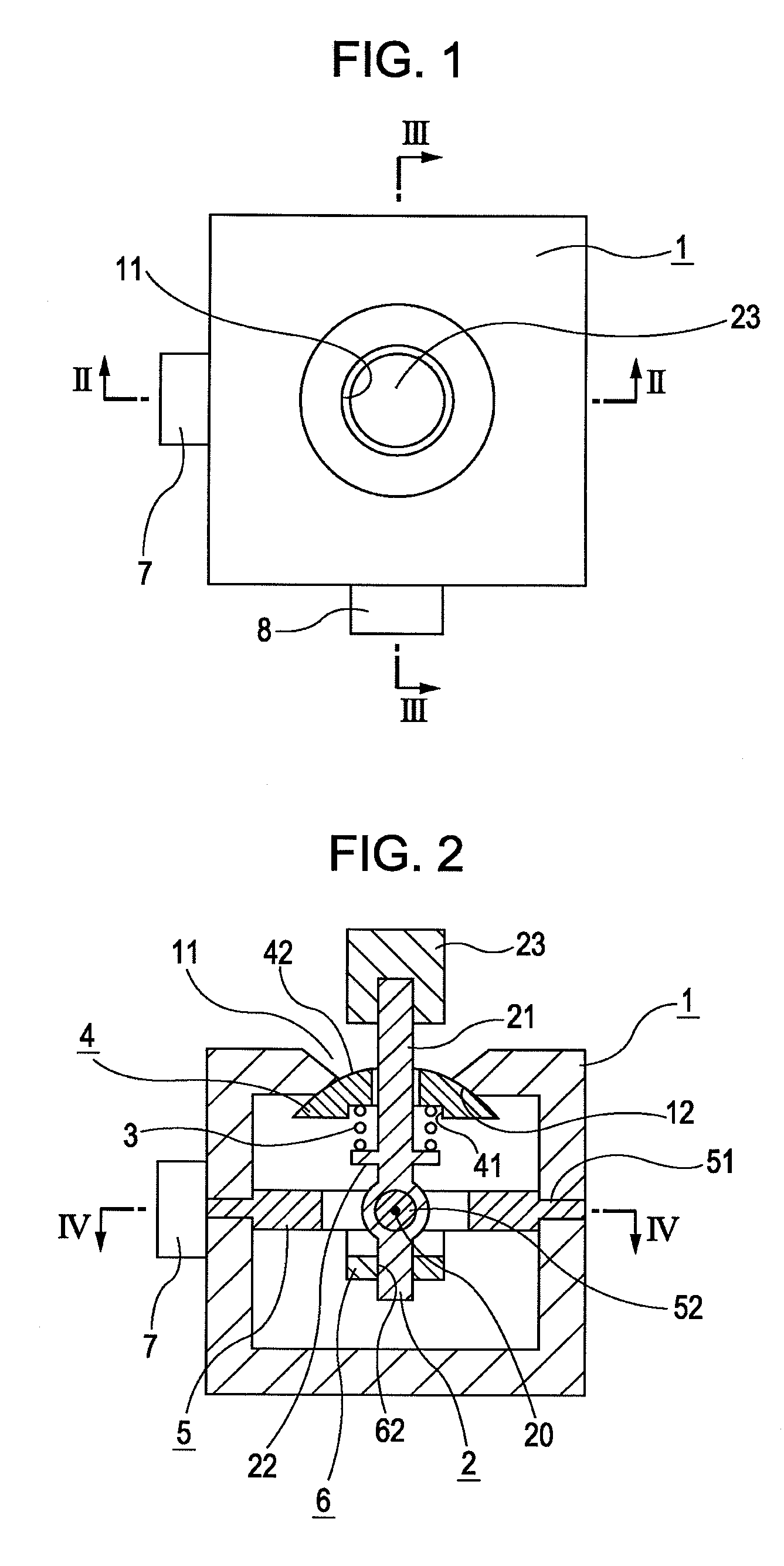
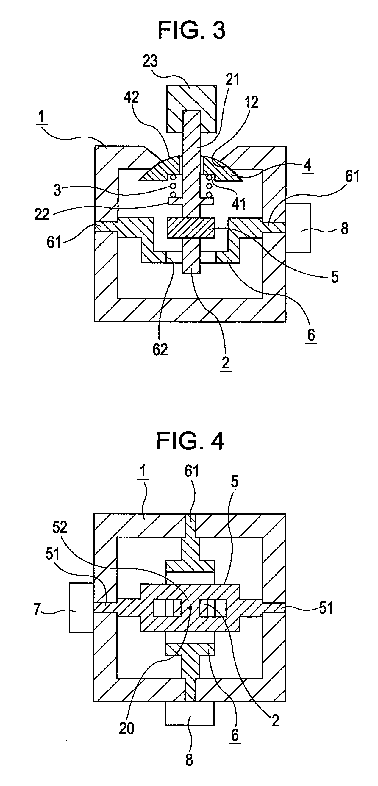
[0029]Embodiments of the present invention will be described with reference to the accompanying drawings. FIG. 1 is a top view of a multi-directional input apparatus according to the present invention. FIG. 2 is a sectional view of FIG. 1 taken along line II-II, FIG. 3 is a sectional view of FIG. 1 taken along line III-III, and FIG. 4 is a sectional view of FIG. 2 taken along line IV-IV.

[0030]The multi-directional input apparatus shown in the above-mentioned figures basically includes a box-shaped housing 1 which serves as a restraining member; an operating member 2 which includes a shaft portion 21 and which is capable of being tilted; a coil spring 3 held by the shaft portion 21 of the operating member 2; a dome-shaped sliding member 4 which is elastically biased by the coil spring 3; a first interlocking member 5 and a second interlocking member 6 which are moved when the operating member 2 is operated; a first detector 7 which detects a change in the position of the first interl...

second embodiment

[0042]FIG. 5 is a sectional view of a multi-directional input apparatus according to the present invention. In FIG. 5, components similar to those in FIG. 2 are denoted by the same reference numerals.

[0043]The structure of the multi-directional input apparatus shown in FIG. 5 is basically similar to that of the multi-directional input apparatus according to the first embodiment except the shapes of the sliding member 4 and the receiving surface 12. In the multi-directional input apparatus according to the second embodiment, a plate-shaped sliding member 4 is formed so as to cover the receiving surface 12. An outer peripheral surface of the sliding member 4 serves as a band-shaped, curved rubbing surface 42, and the rubbing surface 42 is in elastic contact with the receiving surface 12, which is a circular bowl-shaped curved surface, at various areas in accordance with the tilting direction and the tilting angle of the shaft portion 21. Also in the present embodiment, the rubbing sur...


PUM


Abstract

A multi-directional input apparatus includes an operating member including a shaft portion which extends to the outside, a housing having an opening through which the shaft portion extends and configured to support the operating member in a tiltable manner, interlocking members moved by the operating member when the shaft portion is tilted, and detectors which detect changes in the positions of the interlocking members. A sliding member is externally fitted to the shaft portion such that the sliding member is movable in an axial direction, and a coil spring is disposed between a flange provided on the shaft portion and the sliding member. A rubbing surface of the sliding member is in elastic contact with a receiving surface on an inner wall of an annular edge portion surrounding the opening. The rubbing surface and the receiving surface are spherical surfaces centered on a tilting center of the shaft portion.

Description

CLAIM OF PRIORITY[0001]This application claims benefit of the Japanese Patent Application No. 2008-120304 filed on May 2, 2008 and No. 2008-206847 filed on Aug. 11, 2008, which are hereby incorporated by reference.BACKGROUND OF THE INVENTION[0002]1. Field of the Invention[0003]The present invention relates to a multi-directional input apparatus which includes an operating member provided with a shaft portion and which outputs an electric signal in accordance with a tilting direction and a tilting angle of the shaft portion when the shaft portion is tilted. More specifically, the present invention relates to a technique for suppressing rattling of the shaft portion of the operating member which can be tilted in multiple directions.[0004]2. Description of the Related Art[0005]In this type of multi-directional input apparatus, when an operating force is applied such that the shaft portion of the operating member is tilted, positions of a pair of interlocking members driven by the opera...

Claims


Application Information

Patent Timeline
Patent Type & Authority Patents(United States)
IPC IPC(8): H01C10/16H01H9/00
CPCG05G9/047G05G25/02G05G2009/04714G06F3/0338H01C10/14A63F13/24
Inventor ISHIKAWA, SHINJIKUTSUNA, KUNIHARUYAMAZAKI, YASUHIKO
Owner ALPS ALPINE CO LTD
Why Eureka
Try Eureka