
Passively cooled container system and method

a container system and passive cooling technology, applied in the field of aisle systems, can solve the problems of reducing the payload capacity, reducing the overall utility of the aircraft, and adding to the overall weight of the mechanical refrigeration uni

Active Publication Date: 2016-04-05
THE BOEING CO
View PDF25 Cites 32 Cited by
  • Summary
  • Abstract
  • Description
  • Claims
  • Application Information

AI Technical Summary

Benefits of technology

The present patent proposes a system for refrigerating the interior of a container, such as a galley cart, using a cold tray that can be installed inside the container and containing a refrigerant. The cold tray is designed to draw air from the interior of the container and cool it using the refrigerant before returning it back into the container. The system can be used in a variety of applications and is particularly useful in aircraft to maintain a stable temperature for food and other items. The technical effects of the system include improved food cooling, reduced energy consumption, and improved preservation of perishable items.

Problems solved by technology

Although generally effective for their intended purposes, galley chillers possess certain drawbacks which detract from their overall utility.
The mechanical refrigeration units add to the overall weight of the aircraft reducing payload capacity and increasing fuel consumption.
In addition, mechanical refrigeration units typically produce noise that adds to aircraft cabin noise and reduces passenger comfort.
A further drawback associated with conventional galley chillers is that the refrigeration units and associated ducting occupy valuable space in the galleys which reduces the total amount of cabin area available for passenger seating
Additional drawbacks associated with conventional galley chillers include relatively high manufacturing and installation costs due to the complexity of the mechanical refrigeration units.
Furthermore, the mechanical refrigeration units typically require routine maintenance at regular service intervals which adds to the operating costs of the aircraft.
In addition, the mechanical refrigeration units may consume significant amounts of electrical power which must be provided by the aircraft power system.
To accommodate the power requirements, the galley chiller may require heavy gauge electrical feeder lines and associated circuit breakers, all of which adds to the weight and space requirements of the aircraft.

Method used


Image

  • Passively cooled container system and method
  • Passively cooled container system and method
  • Passively cooled container system and method

Examples


Embodiment Construction

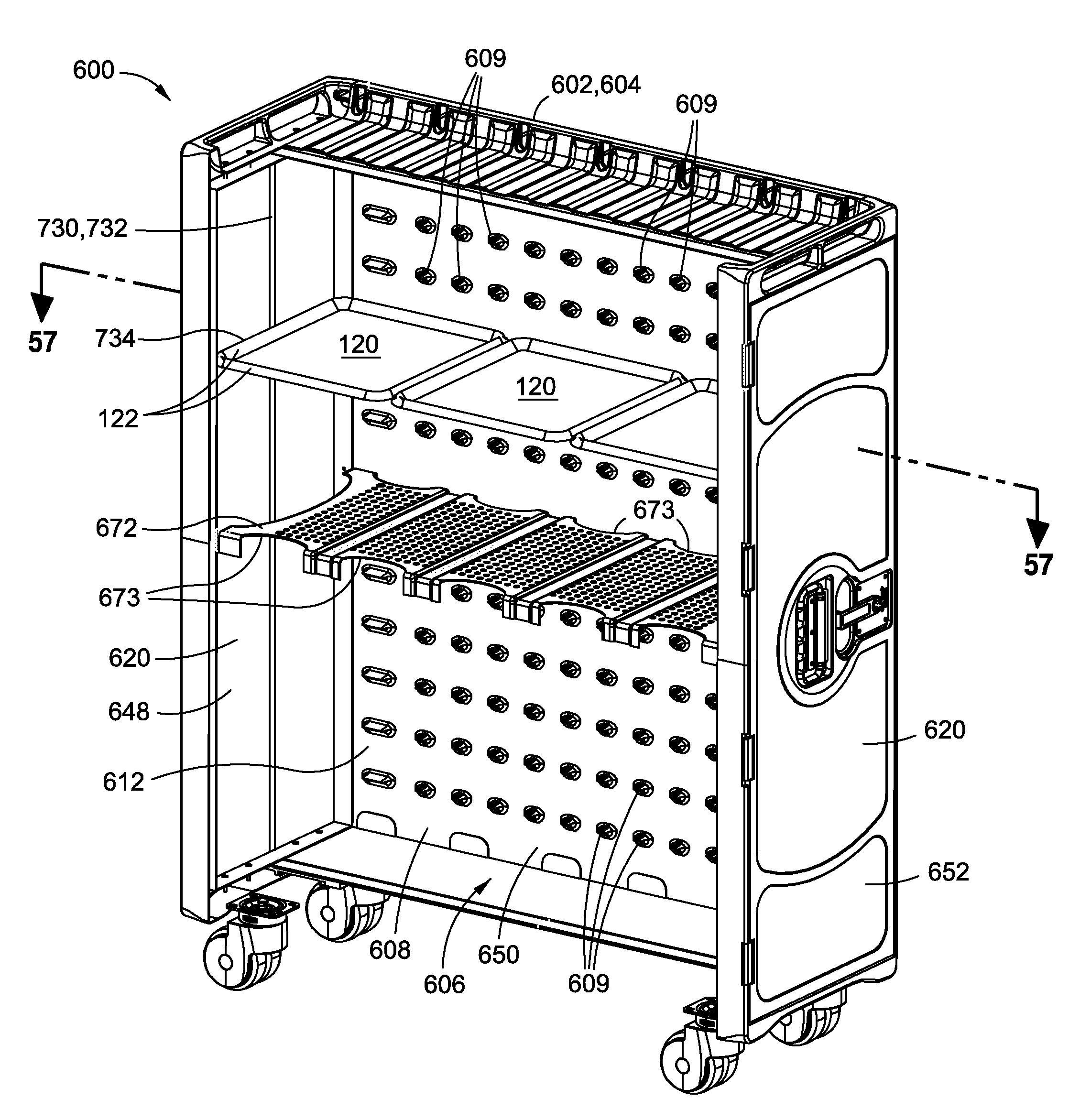
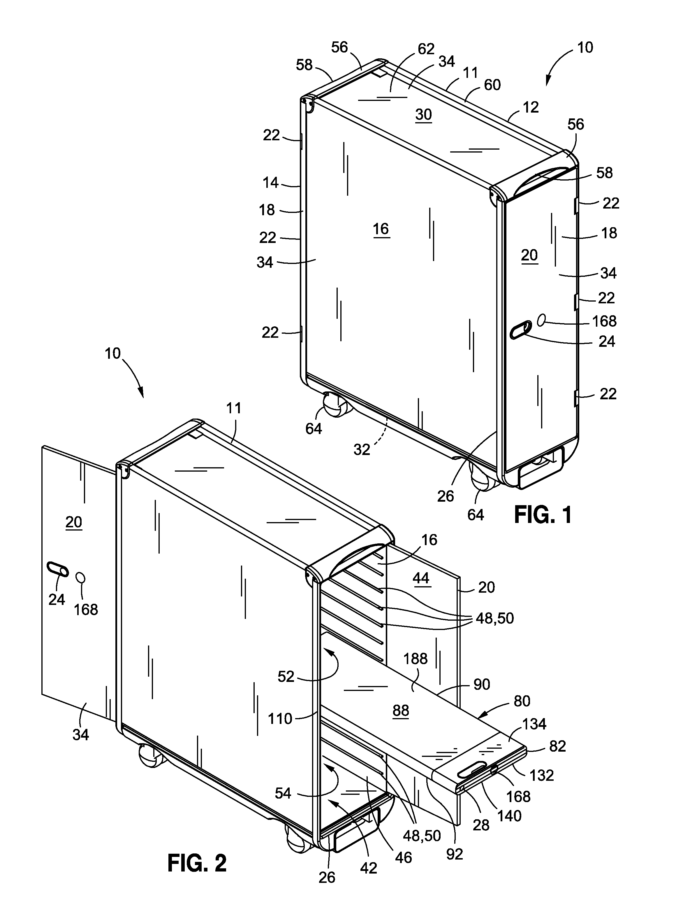
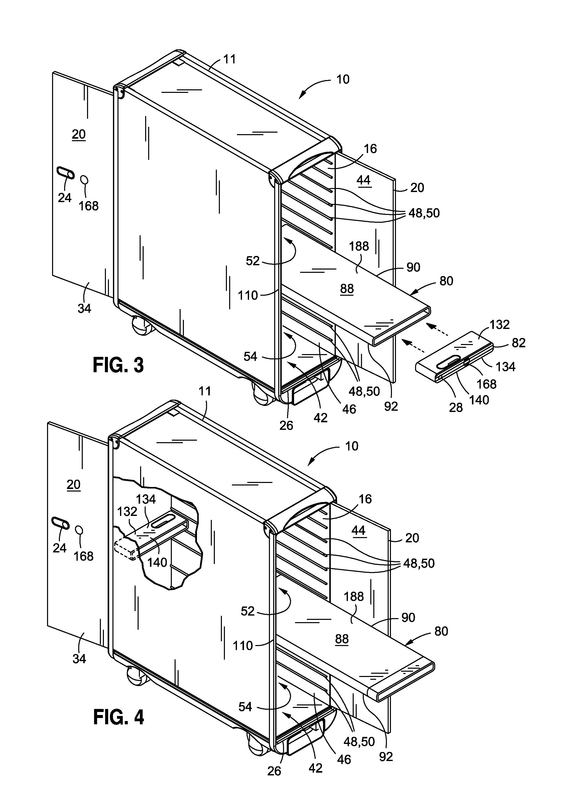
[0090]Referring now to the drawings wherein the showings are for purposes of illustrating preferred and various embodiments of the disclosure, shown in FIGS. 1-8 is a container system 10 as may be used in an aircraft cabin. The container system 10 may comprise an insulated galley cart 12 housing a cold tray 80 (FIG. 2) containing refrigerant (FIG. 2). The cold tray 80 is insertable within a container interior 42 of the galley cart 12 for maintaining food or other items stored within the galley cart 12 at a safe temperature. The cold tray 80 comprises a self-contained cooling unit that, when installed within the galley cart 12, may maintain the air temperature of the container interior 42 below a desired temperature. For example the cold tray 80 may maintain the container interior 42 at between approximately 0° C. and approximately 7° C. for extended durations of up to 15 hours or longer. However, the galley cart 12 and the cold tray 80 may be configured to maintain the air temperatu...


PUM


Abstract

A container system may comprise a container, a refrigerant tray, and refrigerant. The container may have a container interior. The refrigerant tray may be mountable within the container interior and may include a sublimation port. The refrigerant may be mounted within the refrigerant tray. The refrigerant may produce a cold gas upon sublimation of the refrigerant. The cold gas may pass through the sublimation port and enter into the container interior.

Description

CROSS-REFERENCE TO RELATED APPLICATIONS[0001]The present application is a continuation-in-part of and claims priority to pending U.S. patent application Ser. No. 12 / 778,096 entitled REFRIGERATED CONTAINER filed on May 11, 2010, the entire contents of which is incorporated by reference herein.STATEMENT RE: FEDERALLY SPONSORED RESEARCH / DEVELOPMENT[0002](Not Applicable)FIELD[0003]The present disclosure relates generally to galley systems and, more particularly, to a container for refrigerating items such as airline meals prior to distribution to passengers.BACKGROUND[0004]Aircraft galley carts are used to store food items such as airline meals for distribution to passengers by flight attendants. Airline meals are typically prepared offsite by a caterer who then delivers the meals to the aircraft just prior to departure. Airline operators are required to maintain food items at a safe temperature prior to distribution to passengers. For certain long-haul flights, the food items must be c...

Claims


Application Information

Patent Timeline
IPC IPC(8): F25D3/12A47B31/02A47B96/02F25D17/04F25D25/02A47B31/00
CPCA47B96/021A47B31/02F25D17/04F25D3/125F25D25/021F25D2303/0844A47B2031/005F25D2331/812B64D11/0007F25D3/06F25D17/06F25D17/045F25D2303/08222
Inventor SCHALLA, JAMES P.HILLS, KAREN L.BROWN, DOUGLAS A.
Owner THE BOEING CO
Learn More