Swash plate type variable displacement compressor
a variable displacement compressor and compressor technology, applied in the direction of fluid-pressure actuators, positive displacement liquid engines, servomotors, etc., can solve the problem of difficult rapid increase of compressor displacement, and achieve the effect of reducing the size of the compressor, increasing the displacement quickly, and simplifying the configuration of the compressor
- Summary
- Abstract
- Description
- Claims
- Application Information
AI Technical Summary
Benefits of technology
Problems solved by technology
Method used
Image
Examples
first embodiment
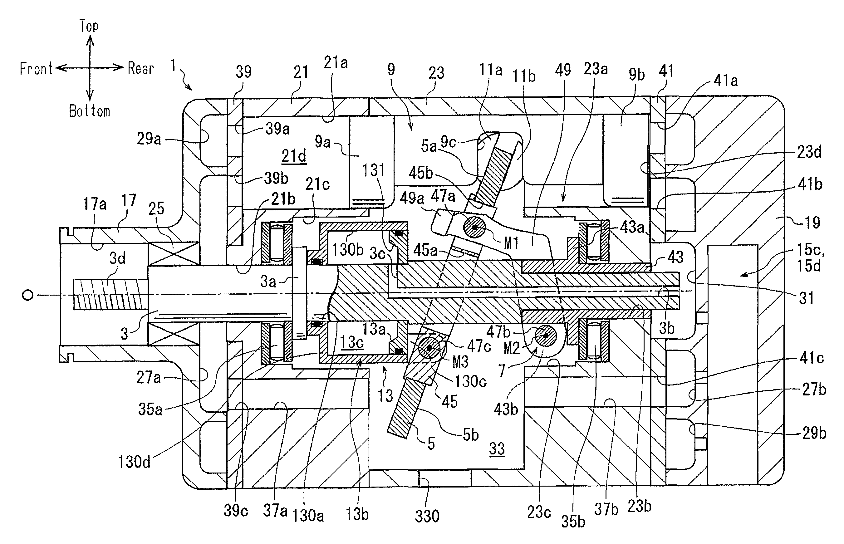
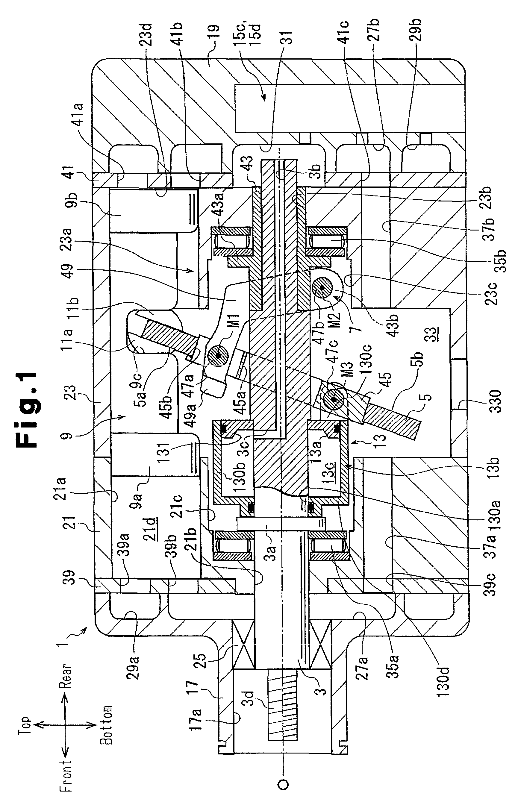
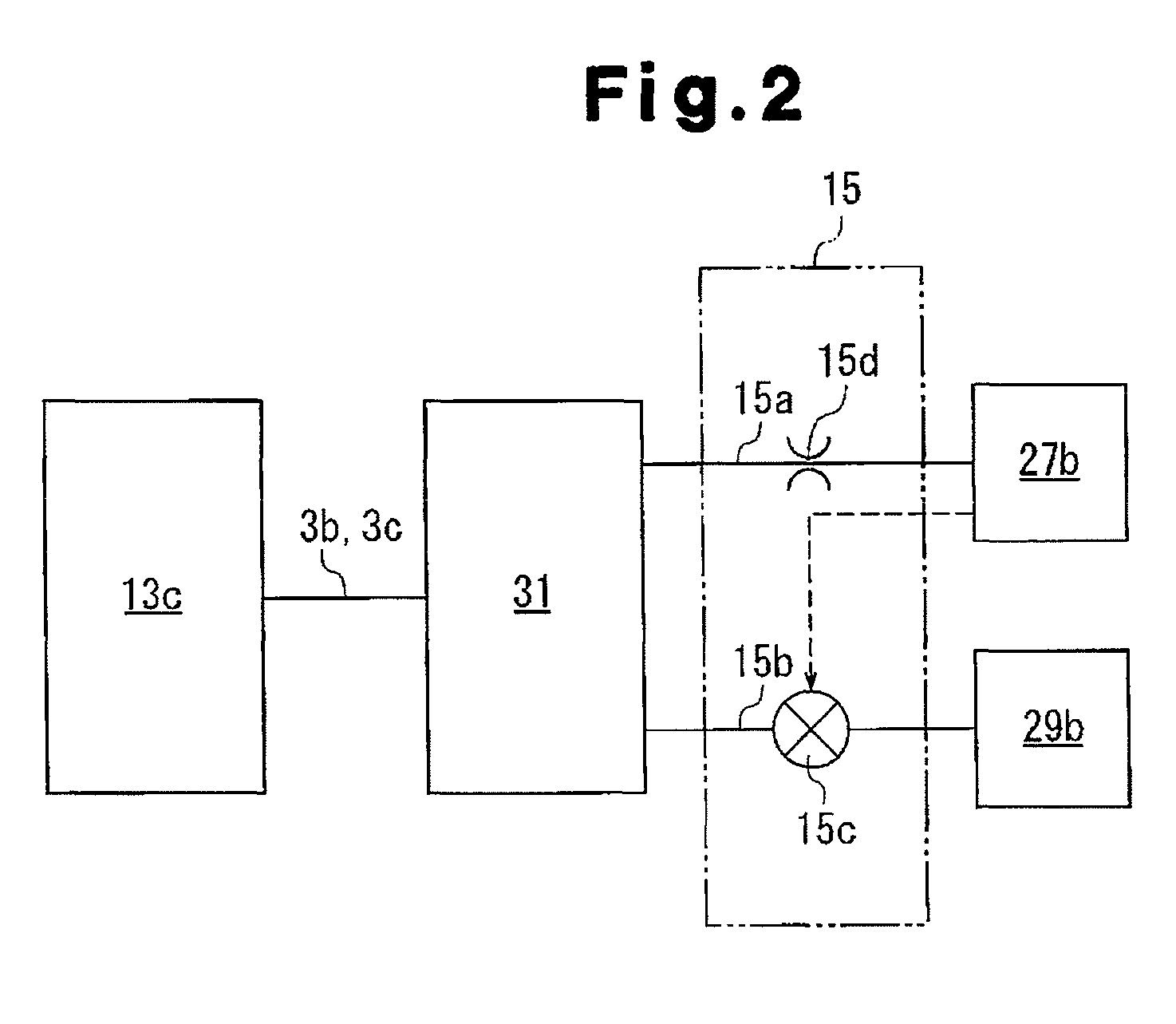
[0019]As shown in FIGS. 1 and 3, a compressor according to a first embodiment of the invention includes a housing 1, a drive shaft 3, a swash plate 5, a link mechanism 7, a plurality of pistons 9, pairs of front and rear shoes 11a, 11b, an actuator 13, and a control mechanism 15, which is illustrated in FIG. 2.
[0020]With reference to FIG. 1, the housing 1 has a front housing member 17 at a front position in the compressor, a rear housing member 19 at a rear position in the compressor, and a first cylinder block 21 and a second cylinder block 23, which are arranged between the front housing member 17 and the rear housing member 19.
[0021]The front housing member 17 has a boss 17a, which projects forward. A shaft sealing device 25 is arranged in the boss 17a and arranged between the inner periphery of the boss 17a and the drive shaft 3. A suction chamber 27a and a first discharge chamber 29a are formed in the front housing member 17. The first suction chamber 27a is arranged at a radia...
second embodiment
[0069]A compressor according to a second embodiment of the invention includes a control mechanism 16 illustrated in FIG. 4, instead of the control mechanism 15 of the compressor of the first embodiment. The control mechanism 16 includes a bleed passage 16a and a supply passage 16b each serving as a control passage, a control valve 16c, and an orifice 16d.
[0070]The bleed passage 16a is connected to the pressure regulation chamber 31 and the second suction chamber 27b. This configuration allows the bleed passage 16a to ensure communication between the control pressure chamber 13c and the second suction chamber 27b. The supply passage 16b is connected to the pressure regulation chamber 31 and the second discharge chamber 29b. The control pressure chamber 13c and the pressure regulation chamber 31 thus communicate with the second discharge chamber 29b through the supply passage 16b. The orifice 16d is formed in the supply passage 16b to restrict the amount of the refrigerant gas flowin...
third embodiment
[0077]As illustrated in FIGS. 5 and 6, a compressor according to a third embodiment of the invention includes a housing 10 and pistons 90, instead of the housing 1 and the pistons 9 of the compressor of the first embodiment.
[0078]The housing 10 has a front housing member 18, in addition to the rear housing member 19 and the second cylinder block 23, which are the same components as those of the first embodiment. The front housing member 18 has a boss 18a projecting forward and a recess 18b. The shaft sealing device 25 is mounted in the boss 18a. Unlike the front housing member 17 of the first embodiment, the front housing member 18 includes neither the first suction chamber 27a nor the first discharge chamber 29a.
[0079]In the compressor, the swash plate chamber 33 is formed by the front housing member 18 and the second cylinder block 23. The swash plate chamber 33 is arranged substantially in the middle of the housing 10 and communicates with the second suction chamber 27b via the ...
PUM
 Abstract
Description
Claims
Application Information
 - R&D
- Intellectual Property
- Life Sciences
- Materials
- Tech Scout
- Unparalleled Data Quality
- Higher Quality Content
- 60% Fewer Hallucinations
Browse by: Latest US Patents, China's latest patents, Technical Efficacy Thesaurus, Application Domain, Technology Topic, Popular Technical Reports.
© 2025 PatSnap. All rights reserved.Legal|Privacy policy|Modern Slavery Act Transparency Statement|Sitemap|About US| Contact US: help@patsnap.com


