
Sensor for measuring tilt angle based on electronic textile and method thereof

a technology of tilt sensor and electronic textile, which is applied in the direction of measuring leads/probes, instruments, weaving, etc., can solve the problems of malfunction, limited application field of tilt sensor constructed as above, and the inability to know the tilt angl

Inactive Publication Date: 2016-04-19
ELECTRONICS & TELECOMM RES INST
View PDF10 Cites 4 Cited by
  • Summary
  • Abstract
  • Description
  • Claims
  • Application Information

AI Technical Summary

Benefits of technology

This solution enables higher resolution tilt angle measurements and functionality even when the metal bead is inverted, expanding the sensor's application fields by reducing measurement errors and improving accuracy.

Problems solved by technology

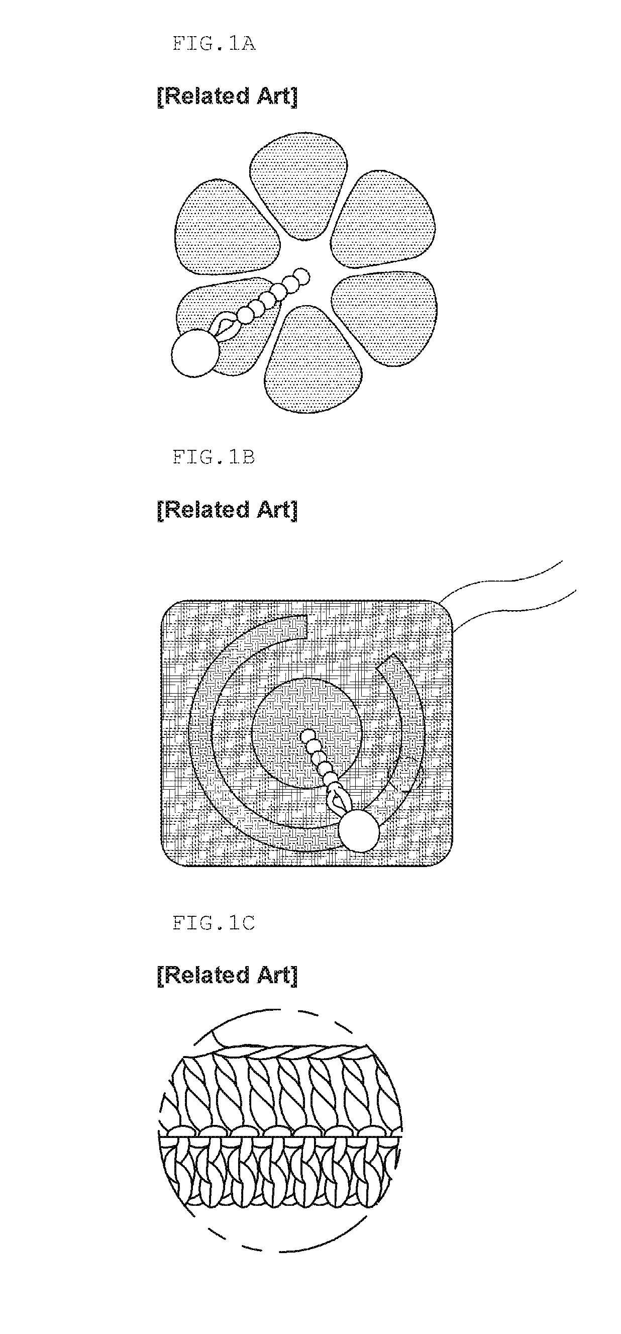
However, the above tilt sensor based on the electronic textile or gradient sensors have many disadvantages.
Therefore, when the metal bead is turned over, it is not possible to know a tilt angle, or there is a need to use two sensors.
When a change in a tilt angle occurs in a direction opposite to a direction of a bead, the bead does not move and thus, a malfunction occurs.
Since a measurement error of a tilt angle is great, an application field applicable with the tilt sensor constructed as above may be limited.

Method used


Image

  • Sensor for measuring tilt angle based on electronic textile and method thereof
  • Sensor for measuring tilt angle based on electronic textile and method thereof
  • Sensor for measuring tilt angle based on electronic textile and method thereof

Examples


Embodiment Construction

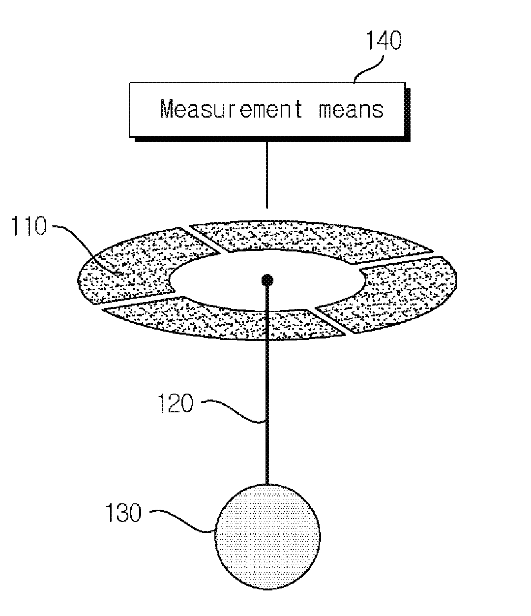
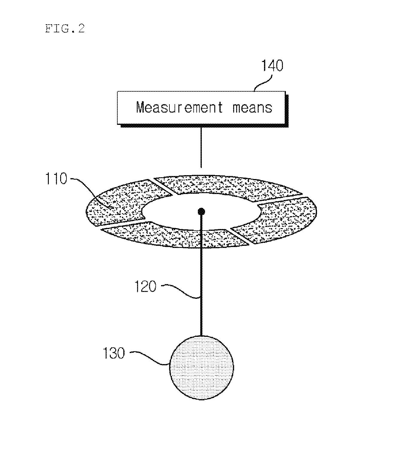
[0030]Hereinafter, a sensor for measuring a tilt angle based on electronic textile according to exemplary embodiments of the present invention and a method thereof will be described in detail with reference to the accompanying FIGS. 2 through 6. Description will be made in detail based on a portion required to understand an operation and effect according to the present invention.

[0031]In particular, the present invention proposes a new tilt sensor based on electronic textile that connects a metal bead to dangle from a center between a plurality of conductive textile electrodes disposed at uniform intervals using a textile conductive wire and in this instance, connects the textile conductive wire using a twisted pair cable connecting scheme.

[0032]FIG. 2 is a diagram illustrating a tilt sensor based on electronic textile according to an exemplary embodiment of the present invention.

[0033]As illustrated in FIG. 2, the tilt sensor based on the electronic textile according to the present...


PUM

PropertyMeasurementUnit
distancesaaaaaaaaaa
lengthaaaaaaaaaa
diameteraaaaaaaaaa

Abstract

Disclosed are a sensor for measuring a tilt angle based on electronic textile according to the present invention and a method thereof. A sensor for measuring a tilt angle based on electronic textile according to the present invention includes a plurality of textile electrodes disposed at predetermined uniform intervals on a textile surface; a textile conductive wire of which one end is connected to a center between the plurality of textile electrodes; and a metal bead connected to another end of the textile conductive wire to thereby be connected to the textile surface.

Description

CROSS-REFERENCE TO RELATED APPLICATIONS[0001]This application claims priority to and the benefit of Korean Patent Application No. 10-2012-0081653 filed in the Korean Intellectual Property Office on Jul. 26, 2012, the entire contents of which are incorporated herein by reference.TECHNICAL FIELD[0002]The present invention relates to a tilt sensor based on electronic textile, and more particularly, to a sensor for measuring a tilt angle based on electronic textile that connects a metal bead to dangle from a center between a plurality of conductive textile electrodes disposed at uniform intervals using a textile conductive wire and in this instance, connects the textile conductive wire using a twisted pair cable connecting scheme, and a method thereof.BACKGROUND ART[0003]Electronic textile refers to a system generated by combining conductive textile, a small electronic part, and the like. Here, the conductive textile is generated by applying conductive yarn, conductive ink, and the like...

Claims


Application Information

Patent Timeline
Patent Type & Authority Patents(United States)
IPC IPC(8): G01R1/06G01B7/30H01L21/00B22F1/00
CPCG01B7/30B22F1/00H01L21/00H01L2221/00G01C9/06D03D11/00
Inventor LEE, HYUNG SUNSHIN, HYUNG CHEOLSTARNER, THAD E.GILLILAND, SCOTT M.ZEAGLER, CLINT
Owner ELECTRONICS & TELECOMM RES INST
Learn More