Projecting illumination device with multiple light sources

a technology of illumination device and light source, which is applied in the direction of projector, lighting and heating apparatus, lighting applications, etc., can solve the problems of inability to meet the requirements of led projecting system, inability to successfully use leds in connection with light application systems, and inability to achieve efficient light emitting area

Active Publication Date: 2016-05-03
MARTIN PROFESSIONAL
View PDF17 Cites 4 Cited by
  • Summary
  • Abstract
  • Description
  • Claims
  • Application Information

AI Technical Summary

Problems solved by technology

However, LEDs have not presently been successfully used in connection with light application systems where an image is created and projected towards a target surface.
LED projecting systems have not yet been able to fulfill these requirements.
The LED is encapsulated into the tube which optically reduces the efficient light emitting area of the LED and it is as a consequence difficult to maintain etendue through the entire optical system.
Further it is difficult to design the focusing properties of the tube as focusing is performed by the hybrid exiting surface which constraints the desing options as only two surfaces parts can be adjusted.
Yet another issue is the fact the high power LED used today often need cooling which is difficult provide when the LED is encapsulated into the tube.
The consequence is, however, that the efficiency with regard to power consumption versus light output is very low.
Furthermore, a large amount of light is lost as the prior art fixtures typically only couple a central part of the light of the light beams through the gate in order to provide a uniform illumination of the gate, which again reduces the efficiency.
The space in light fixtures is often limited and it is difficult to fit many light sources into prior art fixtures, for instance because the optical components associated with the light sources often take up a lot of space.
Yet another aspect is the fact that color artifacts often appear in the output from fixtures having light sources of different colors.

Method used


Image

  • Projecting illumination device with multiple light sources
  • Projecting illumination device with multiple light sources
  • Projecting illumination device with multiple light sources

Examples


Embodiment Construction

[0009]The objective of the present invention is to solve or minimize at least some of the above described problems. This can be achieved by the invention as defined by the independent claims. The benefits and advantages of the present invention are disclosed in the detailed description of the drawings illustrating the invention. The dependent claims define different embodiments of the invention.

DESCRIPTION OF THE DRAWING

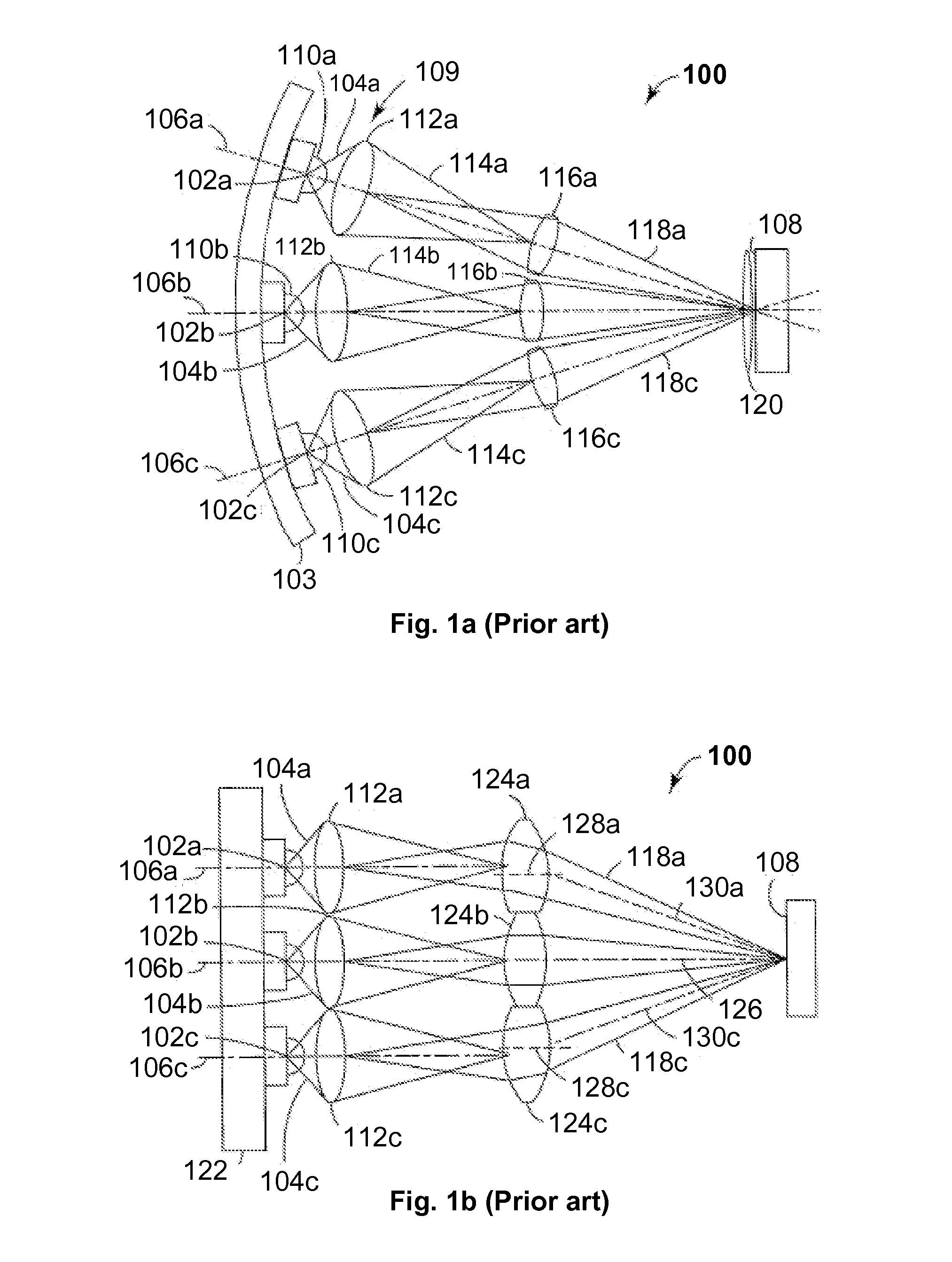
[0010]FIGS. 1a and 1b illustrate a prior art illumination system comprising a number of LEDs;

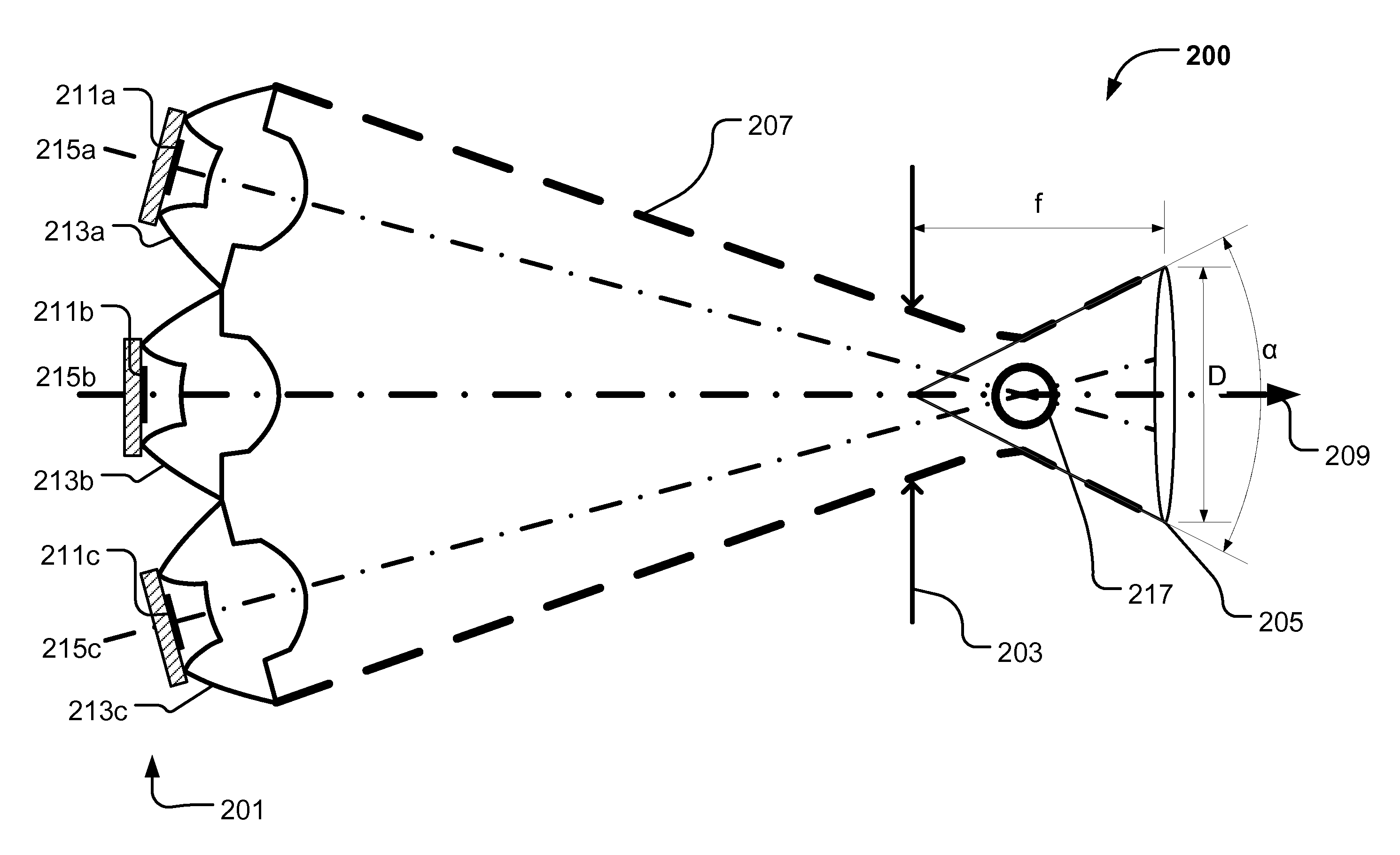
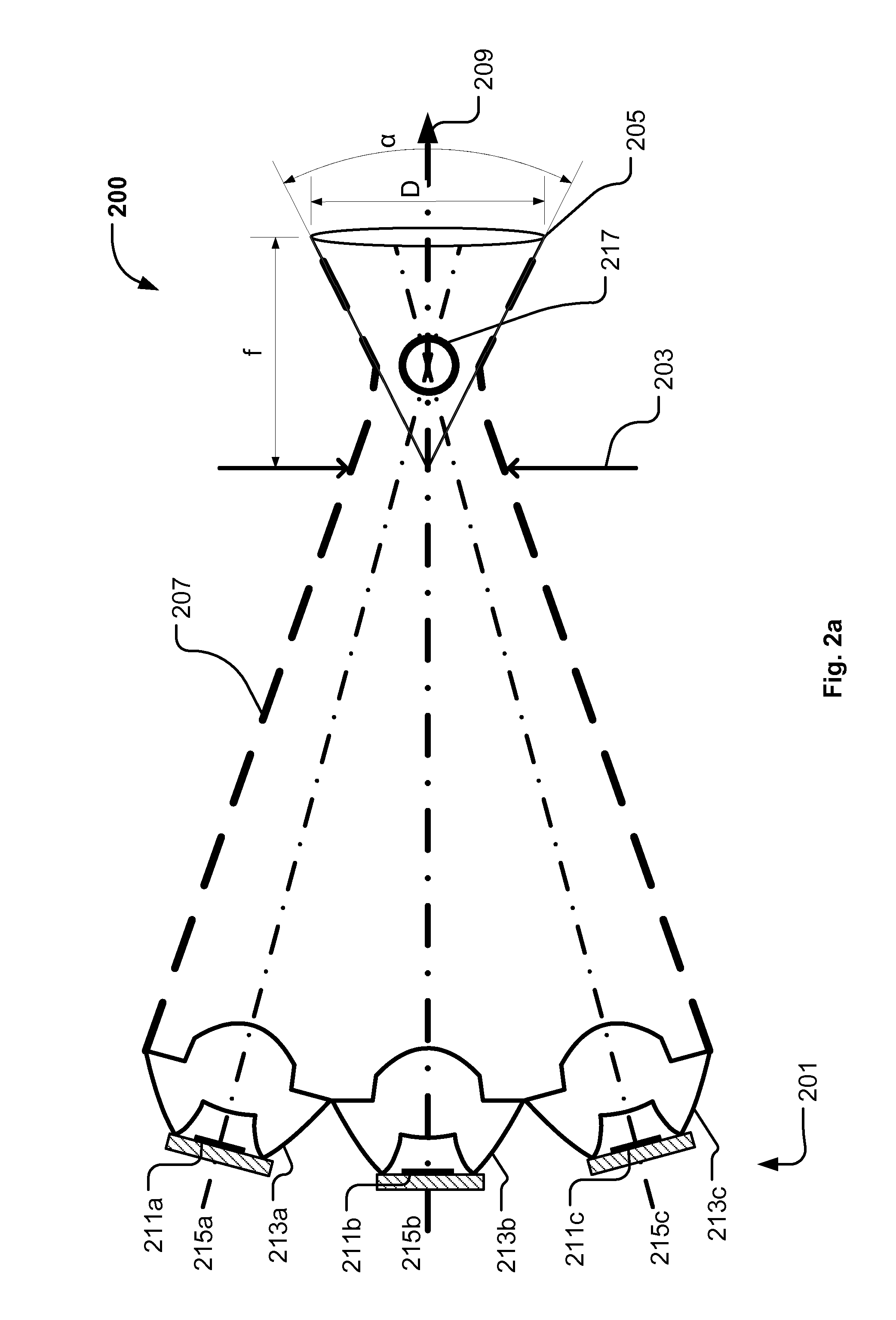
[0011]FIGS. 2a and 2b illustrate an illumination device according to the present invention;

[0012]FIGS. 3a and 3b illustrate different setups of the light source and light collection means in the illumination device according to the present invention;

[0013]FIG. 4 illustrates a setup where the light source and the light collection means have been tilted and positioned in an offset manner;

[0014]FIGS. 5a and 5b illustrate an embodiment of the illumination device according to the ...


PUM


Abstract

The present invention relates to an illumination device illuminating an optical gate and projecting an image of the optical gate towards a target surface. The illumination device comprises a light source module generation light, an aperture delimiting the optical gate and a projecting system adapted to image the optical gate at a target surface. The light source module comprises a number of light sources and a number of light collecting means. The light collecting means comprise a central lens aligned along and a peripheral lens at least partially surrounding the central lens. The central lens collects and converts a first part of the light from the light source images the light source between the aperture the projecting system. The peripheral lens part collects and converts a second part of said light from said light source and is adapted to concentrate said second part of said light at said aperture.

Description

FIELD OF THE INVENTION[0001]The present invention relates to an illumination device illuminating an optical gate and projecting an image of the optical gate towards a target surface. The illumination device comprises a light source module generating light, an aperture delimiting the optical gate and a projecting system adapted to project the optical gate at a target surface.BACKGROUND OF THE INVENTION[0002]Light emitting diodes (LED) are, due to their relatively low energy consumption, long lifetime, and capability of electronic dimming, becoming more and more used in connection with lighting applications. LEDs are successfully used in lighting applications for general illumination such as, wash / flood lights illuminating a wide area or for generating wide light beams e.g. for the entertainment industry.[0003]However, LEDs have not presently been successfully used in connection with light application systems where an image is created and projected towards a target surface. This is es...

Claims


Application Information

Patent Timeline
Patent Type & Authority Patents(United States)
IPC IPC(8): G09G5/10G02B27/09G02B19/00G03B21/20F21V7/00F21V5/04F21S10/00G02B26/00F21V19/00F21W131/406
CPCG02B26/007F21S10/007F21V5/04F21V7/0091G02B19/0014G02B19/0028G02B19/0061G02B19/0066G02B27/0905G02B27/0955G03B21/20F21V19/001F21W2131/406F21Y2101/02F21Y2115/10
Inventor JORGENSEN, DENNIS THYKJAER
Owner MARTIN PROFESSIONAL
Why Eureka
Try Eureka