
Triangular lift frame with load blocks

a triangular lift frame and load technology, applied in the direction of swivels, load-engaging elements, transportation and packaging, etc., can solve the problems of difficult implementation, damage to components, and uneven weight distribution of components,

Inactive Publication Date: 2016-06-21
GENERAL ELECTRIC CO
View PDF13 Cites 3 Cited by
  • Summary
  • Abstract
  • Description
  • Claims
  • Application Information

AI Technical Summary

Benefits of technology

The triangular lift frame ensures safe handling and maintains full lifting capacity of industrial components by eliminating contact and interference during lifting, reducing the risk of damage and associated costs while accommodating non-symmetric loads.

Problems solved by technology

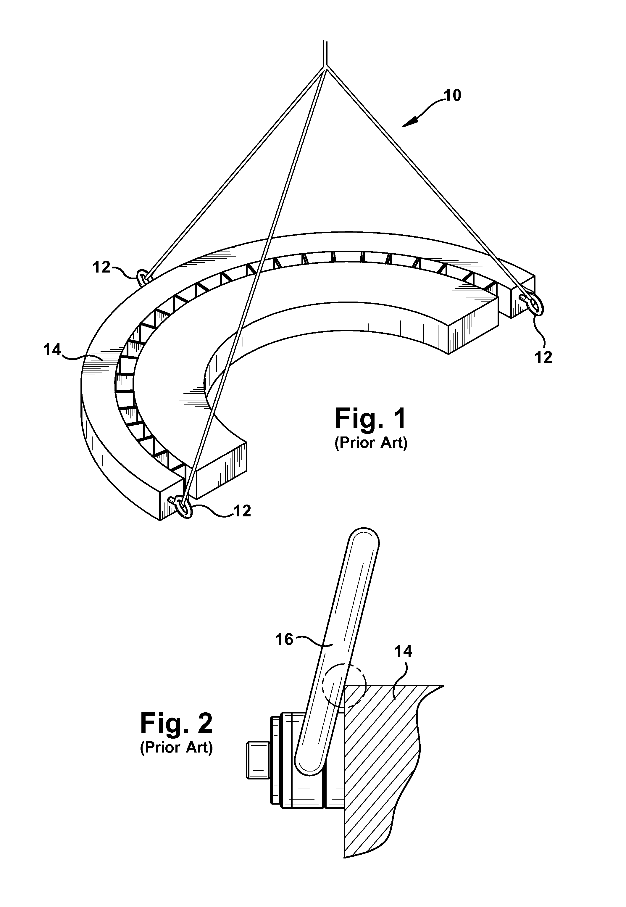
Currently, lifting a component that does not have evenly distributed weight and / or has non-symmetrical connection points, presents a number of challenges.
One challenge is that the rigging arrangement may lead to damage of the component load.
One approach to minimize risk in this situation has been to reduce the size of the eyelet, but this is difficult to implement in the field.
This approach presents a number of challenges because the gussets, welds and frame members are all carrying the load of the component.
In addition, since the gussets are simply vertically welded to the frame members, the load transmission to the frame members may include an amount of torsion on the frame members and / or shear on the welds.
Application of this approach therefore can be limited.
In any conventional approach, damage to industrial components, such as turbine diaphragms, due to improper lifting can result in required repairs resulting in delivery delays and unnecessary costs.
In the steam turbine setting, the costs can be extensive considering hundreds of steam turbine diaphragms may be handled each year during plant outages and repair activities in service shops.
Similar damage and cost problems exist for other industries.

Method used


Image

  • Triangular lift frame with load blocks
  • Triangular lift frame with load blocks
  • Triangular lift frame with load blocks

Examples


Embodiment Construction

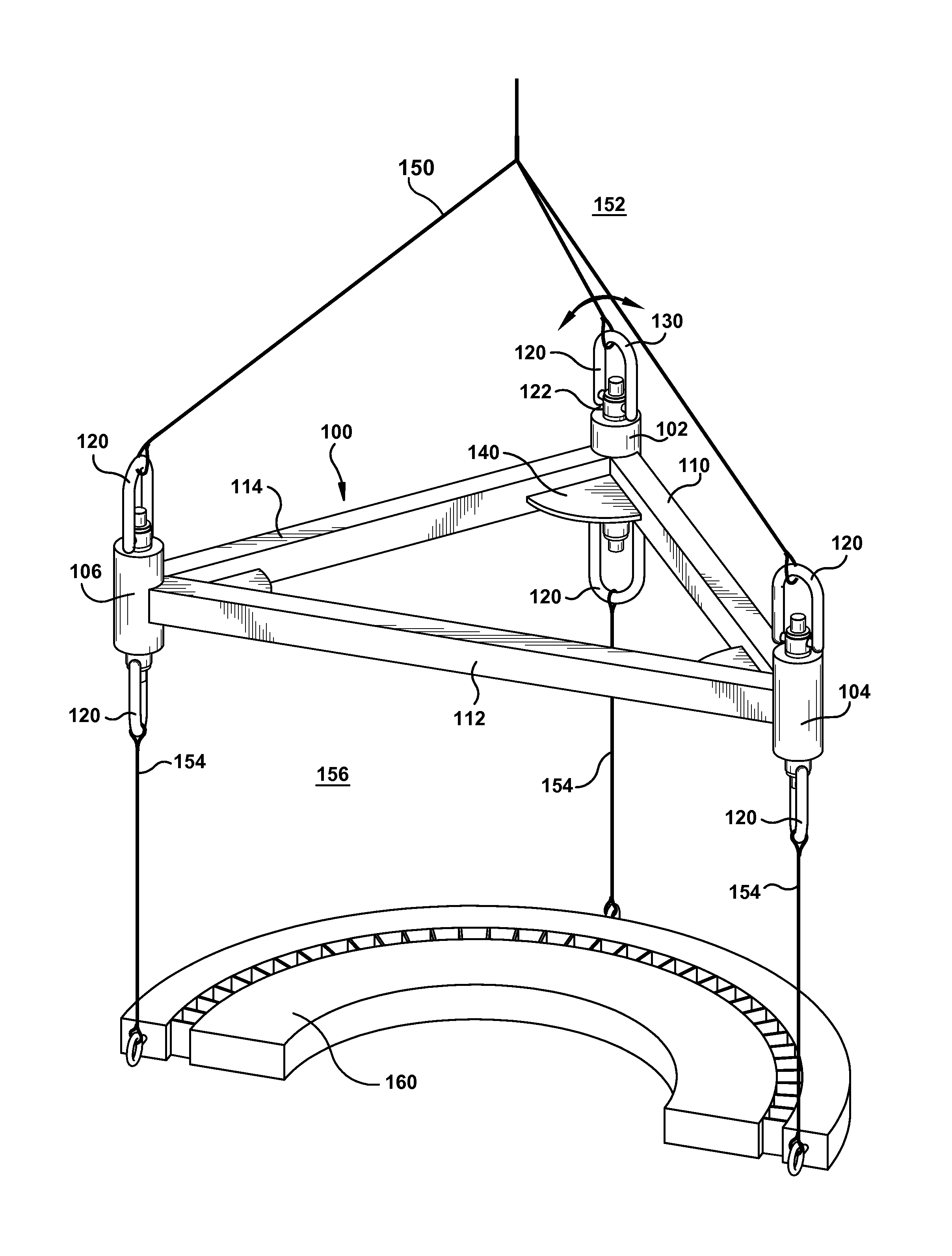
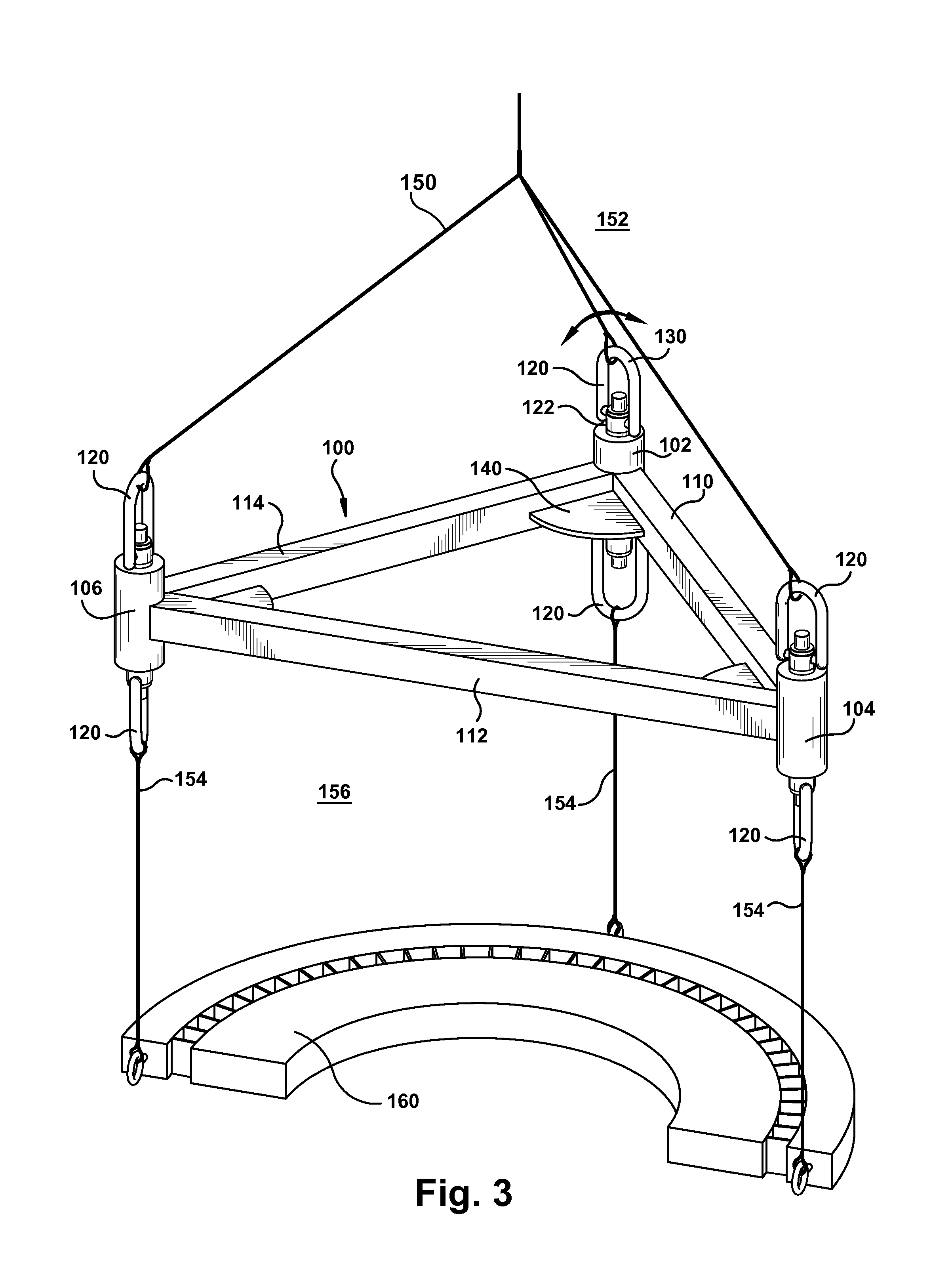
[0017]As indicated above, the disclosure provides a lift frame that is triangular. Lift frame 100, also sometimes referred to as a lifting strongback, allows safe handling of non-symmetric vertical load components, e.g., with 3 non-symmetric load connection points, and allows a single hook to lift the load through the use of unique and custom-shaped, corner load blocks. The lift frame improves and enhances the safety involved with lifting industrial components (such as but not limited to turbine components such as steam turbine diaphragm halves), and maintains the full lifting capacity of rigging components. The load blocks allow for the full load transfer through the block from a vertical orientation to an angular orientation, and linearly longitudinally to the frame members. The use of the load blocks allows for a vertical connection to the component and eliminates the contact and interference that causes damage and the need for rework of the component. The use of the load blocks,...


PUM


Abstract

A triangular lift frame may include a first load block, a second load block and a third lift block, each load block including a hoist ring at each end. A first frame member extends between the first and second load blocks; a second frame member extends between the second and third load blocks; and a third frame member extends between the first and third load blocks. The frame members are arranged in a triangular fashion. In one embodiment, the triangular fashion may be such that a load force carried by each respective pair of load blocks is transmitted linearly longitudinally along a respective frame member extending between the respective pair of load blocks.

Description

BACKGROUND OF THE INVENTION[0001]The disclosure relates generally to lifting devices, and more particularly, to a triangular lift frame having load blocks for component loads such as a steam turbine component.[0002]Currently, lifting a component that does not have evenly distributed weight and / or has non-symmetrical connection points, presents a number of challenges. One challenge is that the rigging arrangement may lead to damage of the component load. For example, FIG. 1 shows a three-legged bridle 10 coupled to eyelets 12 mounted directly on component 14, i.e., a steam turbine diaphragm half. As observed, each leg of the bridle 10 may rub against and damage an edge of component 14 if, for example, accurate crane operation is not implemented. One approach to minimize risk in this situation has been to reduce the size of the eyelet, but this is difficult to implement in the field. As shown in FIG. 2, where a swivel hoist ring 16 is used with a three-legged bridle, the ring may also...

Claims


Application Information

Patent Timeline
Patent Type & Authority Patents(United States)
IPC IPC(8): B66C1/16F16G15/08
CPCB66C1/16F16G15/08B66C1/12
Inventor BERNAT, STEVEN NICHOLAS
Owner GENERAL ELECTRIC CO
Learn More