
Retinal imaging device

a technology of retinal imaging and ophthalmoscope, which is applied in the field of retinal imaging devices, can solve the problems of stray illumination reflection, high operator skill, and reduced gross alignment between the optical system and the patient's pupil,

Active Publication Date: 2016-07-26
REMIDIO INNOVATIVE SOLUTIONS PVT
View PDF17 Cites 13 Cited by
  • Summary
  • Abstract
  • Description
  • Claims
  • Application Information

AI Technical Summary

Benefits of technology

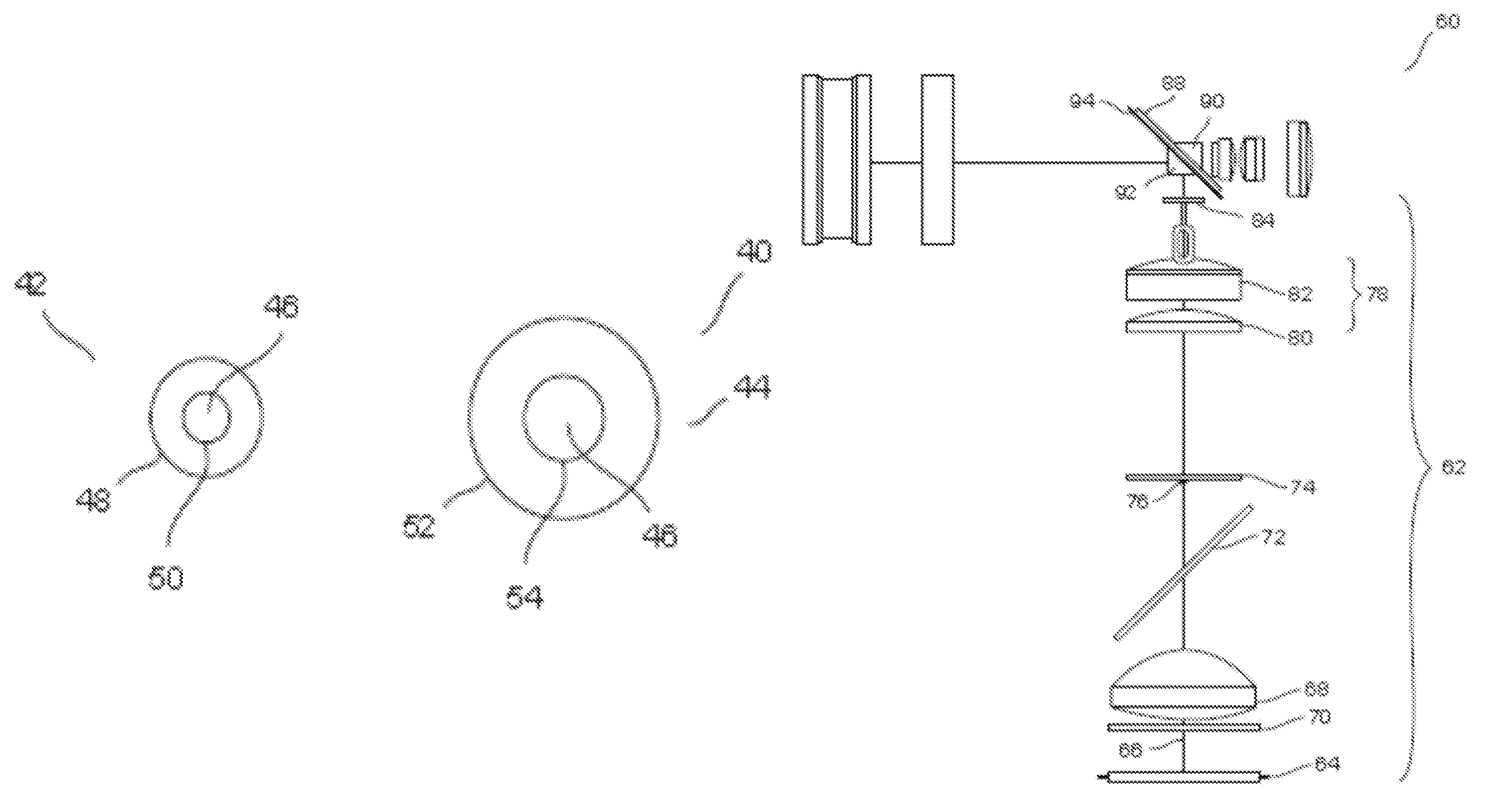
[0015]In one aspect, the invention provides an illumination module for a retinal imaging device. The illumination module includes a light source to provide an incident beam along an illumination axis, a condenser lens placed at a spaced apart distance from the light source for condensing the incident beam and emanating a condensed incident beam, a transparent plate placed at a spaced apart distance from the condenser lens, wherein the transparent plate comprises a light absorber in the form of a black dot, at least one projection lens to focus the condensed incident beam, a shield placed at a spaced apart distance from the projection lens to yield a first partially blocked beam to form a cornea illumination doughnut, and a perforated mirror comprising a hollow cylinder. The perforated mirror is at an angle with respect to the illumination axis and the hollow cylinder is placed perpendicular to the illumination axis and at least a portion of the hollow cylinder protrudes out from a reflecting face of the mirror, forming an elliptical stopper to yield a second partially blocked beam to form a pupil illumination doughnut. The cornea illumination doughnut and the pupil illumination doughnut are aligned in a plane perpendicular to the illumination axis. The use of the protruding hollow cylinder helps significantly reduce unwanted reflections from intraocular lens and the cornea, separates the imaging and illumination paths, and helps create a suitable illumination doughnut, to ensure a high quality reflex-free image.

Problems solved by technology

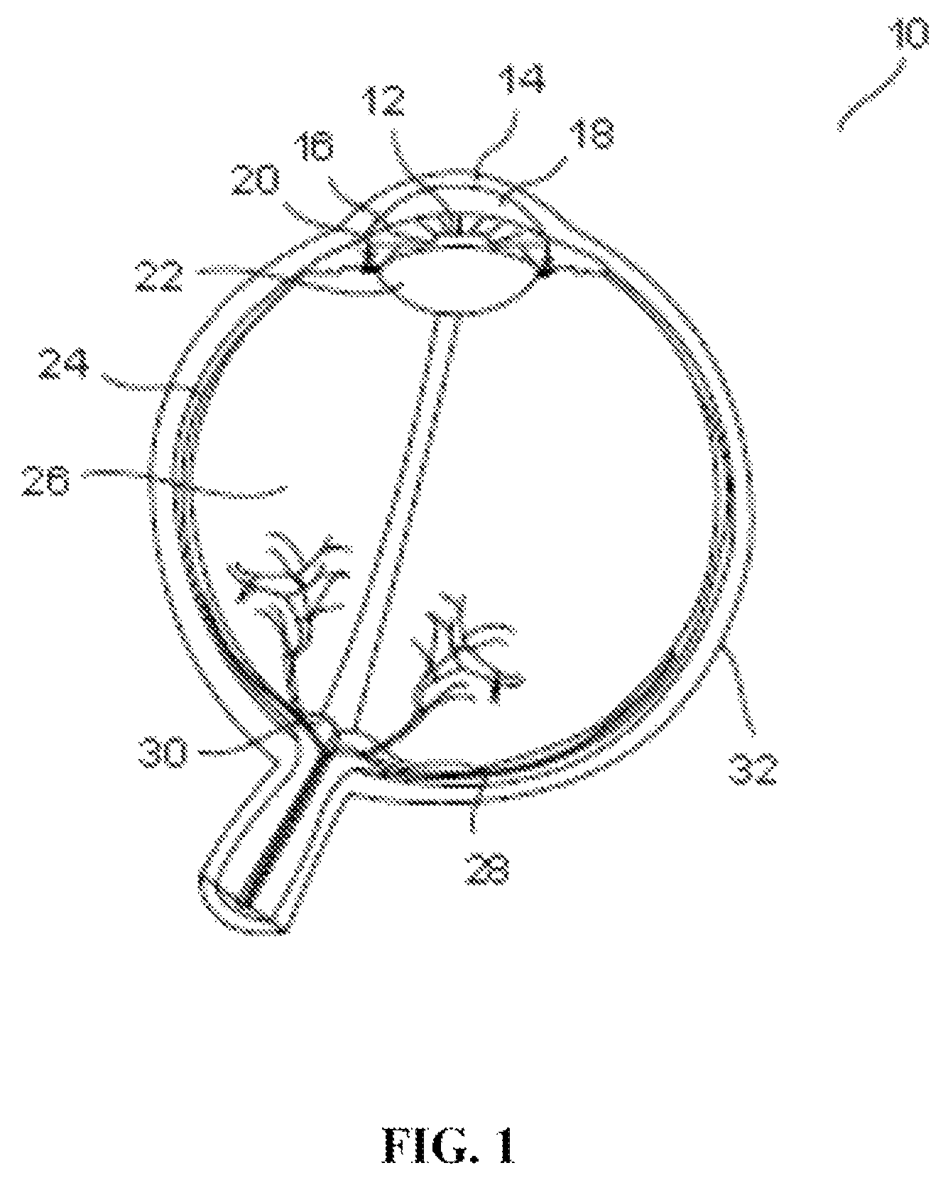
A head restraint for the patient undergoing examination is in the form of a pair of spectacles which is not only easy to use accurately but significantly reduces the gross alignment between the optical system and the patient's pupil.
Though fundus imaging devices have evolved and there have been several improvements in devices for imaging the eye, most of them require high level of operator skill and complex instrumentation.
One significant issue that continues to be a problem is the need to eliminate artifactual reflections from the patient's eye as well as from the lens surfaces used in the optical design of the illuminating and imaging apparatus itself, using as simple and compact an optical design as possible.
The use of simple perforated mirrors have helped separate the imaging and illumination paths, but can in some design embodiments result in both surface reflections as well as stray illumination reflections from still reaching the imaging sensor / imaging eyepiece.

Method used


Image

  • Retinal imaging device
  • Retinal imaging device
  • Retinal imaging device

Examples


Embodiment Construction

[0022]As used herein and in the claims, the singular forms “a,”“an,” and “the” include the plural reference unless the context clearly indicates otherwise.

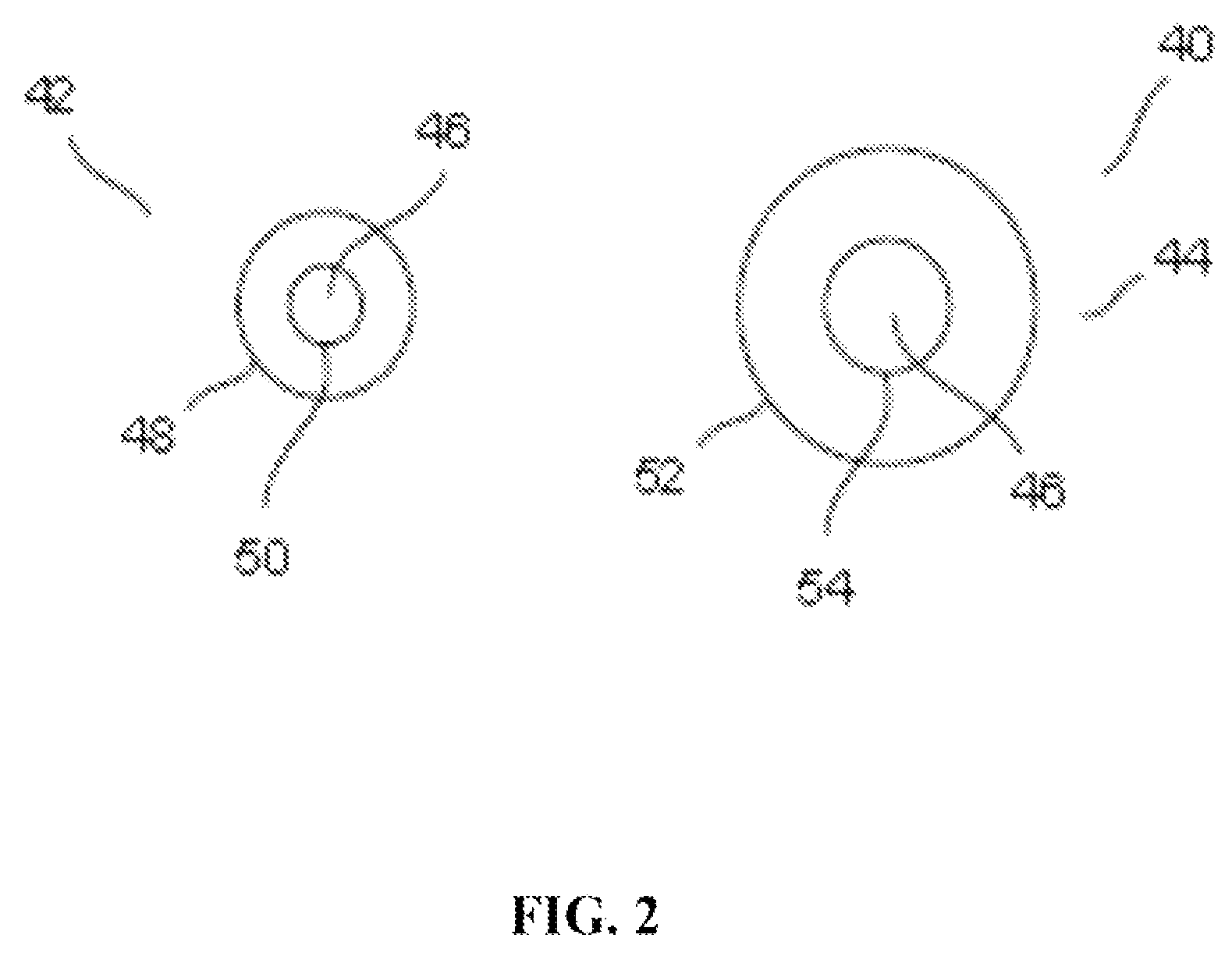
[0023]The aspects of the invention use the Gullstrand principle as mentioned herein above to illuminate and image the retina in novel configurations and methods. In order to obtain a reflection free image, the retinal imaging device of the invention forms two annular imaging rings, one at cornea plane and the other at pupil plane. FIG. 2 is a diagrammatic representation 40 of the two doughnut rings 42 and 44 that are formed at a cornea plane and a pupil plane respectively. As shown, the doughnut ring 42 at the cornea is smaller then the doughnut ring 44 formed at the pupil facilitating imaging of the eye. The imaging is done through the centre dark spot 46 of the doughnut rings to avoid reflections. Each of the doughnut rings 42 and 44 have an outer boundary and inner boundary, shown generally by 48, and 50 for the cornea doughnut...


PUM


Abstract

A retinal imaging device and illumination module. The illumination module includes a light source to provide an incident beam along an illumination axis, a condenser lens at a spaced apart distance from the light source for condensing the incident beam and emanating a condensed incident beam, a transparent plate at a spaced apart distance from the condenser lens, wherein the transparent plate comprises a light absorber, at least one projections lens system to focus the condensed incident beam, a shield at a spaced apart distance from the projection lens system to yield a first partially blocked beam to form a comea illumination doughnut, and a perforated mirror comprising a hollow cylinder. A portion of the hollow cylinder protrudes out from a reflecting face of the mirror, forming an elliptical stopper to yield a second partially blocked beam to form a pupil illumination doughnut, enabling reflex-free imaging of the retina.

Description

CROSS-REFERENCE TO RELATED APPLICATIONS[0001]This application is a U.S. National Phase under 35 U.S.C. 371 to PCT International Patent Application No. PCT / IB2011 / 053764 filed on Aug. 28, 2011 which claims benefit of priority to Indian Patent Application No. 2143 / CHE / 2011 filed Jun. 24, 2011, the contents of both of which are incorporated herein by reference in its entirety.TECHNICAL FIELD[0002]The invention relates generally to a retinal imaging device and more specifically to an imaging of the fundus.BACKGROUND[0003]Ophthalmoscopy (funduscopy or fundoscopy) is a test that allows a clinician to see inside the fundus of the eye and other structures using an ophthalmoscope (or funduscope). It is done as part of an eye examination and is crucial in determining the health of the retina and the vitreous humor. A Direct Ophthalmoscope produces an upright, or unreversed, image of approximately 15 times magnification. The indirect ophthalmoscope produces an inverted, or reversed, direct ima...

Claims


Application Information

Patent Timeline
Patent Type & Authority Patents(United States)
IPC IPC(8): A61B3/14A61B3/15A61B3/00A61B3/12
CPCA61B3/158A61B3/0008A61B3/156A61B3/12
Inventor ANAND, SIVARAMANPRAMOD, KUMMAYASHANMUGANATHAN, NAGARAJAN
Owner REMIDIO INNOVATIVE SOLUTIONS PVT
Learn More