Variable optical attenuator (VOA)

a variable optical and attenuator technology, applied in the field of optical attenuator, can solve the problems of poor transmission quality, affecting the bandwidth capacity of the laser, and it is difficult to achieve high extinction, and achieves low wavelength dependence, high stability, and high extinction.

Inactive Publication Date: 2013-12-31
INLC TECH
View PDF7 Cites 4 Cited by
  • Summary
  • Abstract
  • Description
  • Claims
  • Application Information

AI Technical Summary

Benefits of technology

[0009]In accordance with the present subject matter, a variable optical attenuator with high extinction, low wavelength dependency, high stability, high precision, and small size can be achieved.
[0016]In the variable optical attenuator according to an aspect of the present subject matter, the birefringence control unit may include two substrates substantially parallel to each other and the homeotropic liquid crystal is provided between the two substrates, molecules of the homeotropic liquid crystal being oriented substantially orthogonal to at least one surface of the substrates that contacts with the liquid crystal under no external voltage or current applied thereto, whereby the first and second polarized light beams experience no substantial change of polarization when they pass through the birefringence control unit. It should be noted that a small angle of tilt such as less than 1 or 2 degrees from orthogonal to the substrate can be introduced by properly treating (e.g. rubbing) the surfaces of the substrates to achieve a stable structure and tilt while applying electric field. This will reduce the extinction of the device but the amount is usually very small. The liquid crystal substrate can be also tilted with a small angle to reduce unwanted reflection from the substrate or interference from it. To maintain high extinction of the device, the tilt angle from both the liquid crystal and the substrate can be made parallel or orthogonal to the incoming polarization.

Problems solved by technology

Too much power on the receiver side will saturate the receiver and too little power will result in poor transmission quality.
Although it is possible to simply adjust the electrical current feeding a laser to adjust the output intensity, this is not desirable because this method of attenuation will affect the bandwidth capabilities of the laser.
However, according to the device disclosed in Feng et al., it is very difficult to achieve high extinction due to residual birefringence left in LC module.
It is very cumbersome and quite difficult to match the two cells in exact thickness in practical production.
It also makes the overall device size big, which may result in technical disadvantages.
However, the birefringence can be induced by applying electrical voltage or current.
This will reduce the extinction of the device but the amount is usually very small.

Method used


Image

  • Variable optical attenuator (VOA)
  • Variable optical attenuator (VOA)
  • Variable optical attenuator (VOA)

Examples


Embodiment Construction

[0033]Reference will now be made in detail to embodiments of the present subject matter, examples of which are illustrated in the accompanying drawings, wherein like reference numerals refer to the like elements throughout. The embodiments are described below in order to explain the present subject matter by referring to the figures.

[0034]A variable optical attenuator (VOA) is a device that adjusts optical power ratio between an input light beam and an output light beam over various ranges of the ratio. The VOA is used to attenuate light beams in optical systems such as fiber optic communication systems.

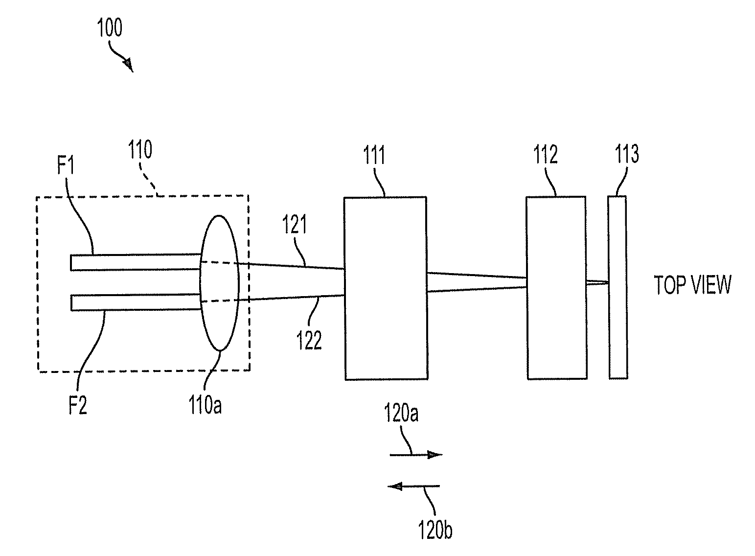
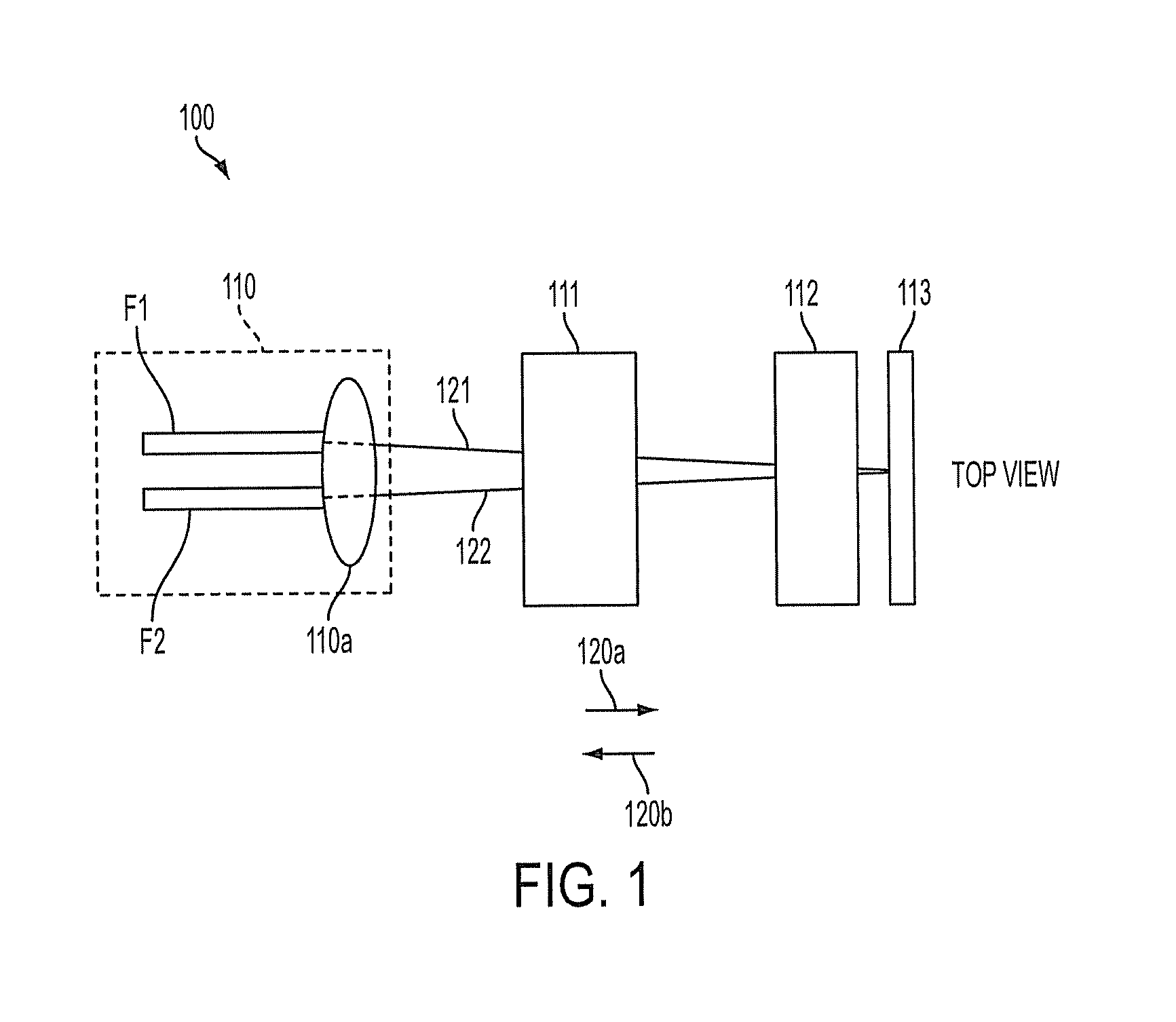
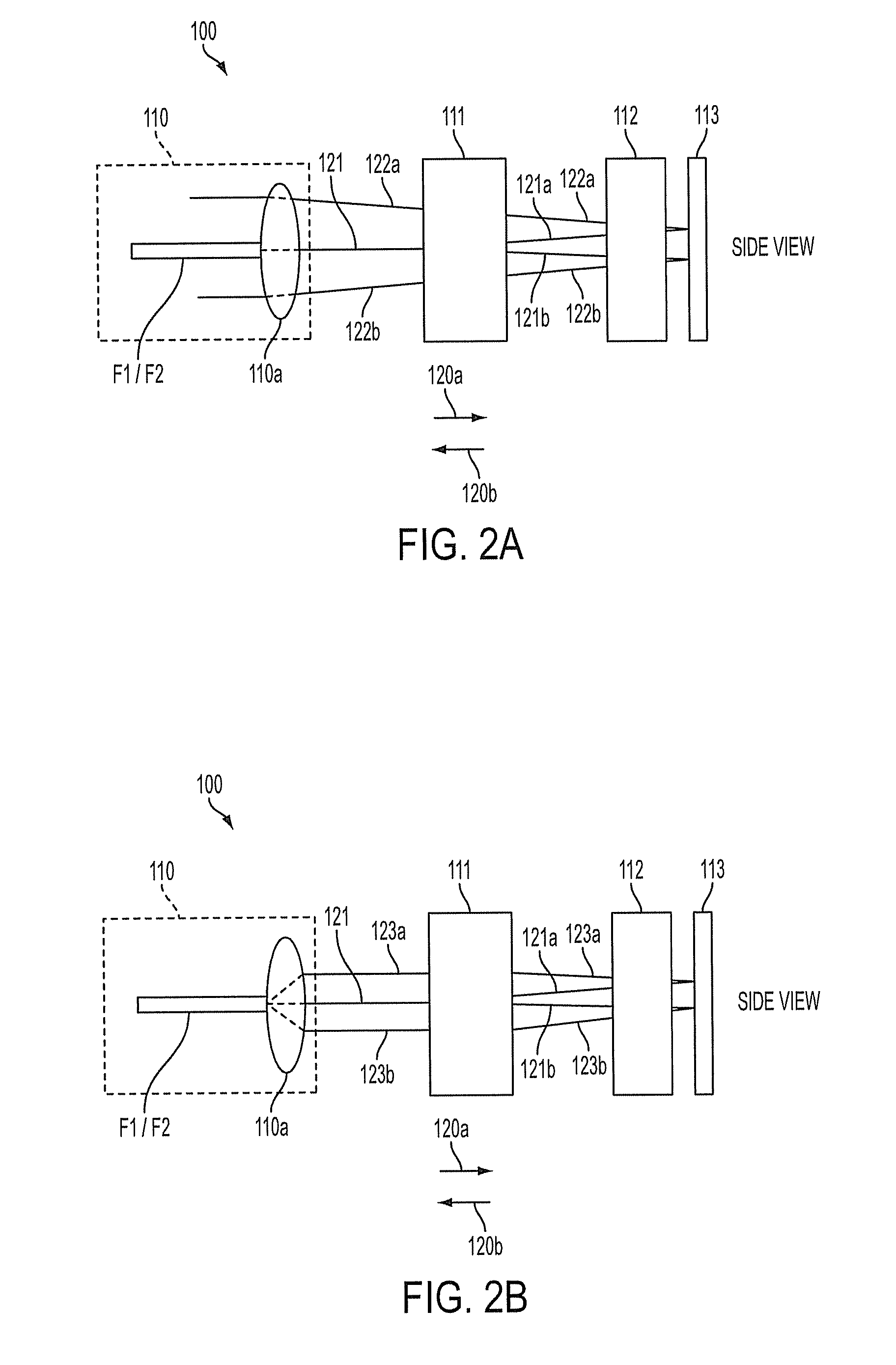
[0035]FIG. 1 is a top view of a variable optical attenuator (VOA) 100 according to an embodiment of the present subject matter. FIGS. 2A and 2B are side views of the VOA 100. The operation principles of the VOA 100 of the present subject matter will be described referring to FIGS. 2A and 2B.

[0036]Referring to FIG. 1, the VOA 100 includes a collimating member 110, a polarization split...


PUM


Abstract

A variable optical attenuator includes a collimating unit that collimates an incident light beam, a polarization splitting member that separates the collimated light beam into a first polarized light beam having a first polarization and a second polarized light beam having a second polarization, a birefringence control unit through which the first and second polarized light beams pass, the birefringence control unit including a liquid crystal cell having a birefringence is controlled by a voltage or current, wherein the birefringence of the liquid crystal cell is substantially zero when no voltage or current is applied thereto, and a reflection member that reflects the first and second polarized light beams output from the birefringence control unit. The variable optical attenuator has high stability, high precision, and low volume.

Description

CROSS-REFERENCE TO RELATED APPLICATION[0001]This application claims the benefit of U.S. Provisional Application No. 61 / 388,062, filed Sep. 30, 2010, in the United States Patent & Trademark Office, the disclosure of which is incorporated herein by reference.BACKGROUND[0002]1. Field[0003]The present subject matter relates generally to the field of optical attenuation devices for use in optical systems, particularly to a variable optical attenuator that requires little space and high stability.[0004]2. Description of the Related Art[0005]Fiber optics is increasingly used for transmitting voice and data signals. As a transmission medium, light provides a number of advantages over traditional electrical communication techniques. For example, light signals allow for extremely high transmission rates and very high bandwidth capabilities. Also, light signals are resistant to electromagnetic interference that would otherwise interfere with electrical signals. Light also provides a more secur...

Claims


Application Information

Patent Timeline
Patent Type & Authority Patents(United States)
IPC IPC(8): G02B6/00
CPCG02B6/266G02F1/1326G02B6/3594G02F2203/48
Inventor SUH, SEONG, WOO
Owner INLC TECH
Why Eureka
Try Eureka