Actuator device, actuation method and manufacturing method

a technology of actuators and actuators, applied in the direction of generators/motors, machines/engines, synthetic resin layered products, etc., can solve problems such as negated deformation

Active Publication Date: 2022-03-15
KONINKLJIJKE PHILIPS NV
View PDF27 Cites 0 Cited by
  • Summary
  • Abstract
  • Description
  • Claims
  • Application Information

AI Technical Summary

Benefits of technology

[0009]The inventors realized that the total force of an actuator is in practice limited by the thickness of the photoresponsive portion (e.g. prior art polymer film) where thin portions cannot exert enough force to be practically useful for actuation. However, while thicker films should be able to provide increased force, it appears that such films will bend somewhat due to the photoresponsive material closer to the light source responding more or faster than photoresponsive material further away from the light source (deeper into the film). This is because the deeper lying material receives less light due to the fact that the light induced activation is based on an absorptive process with a relatively high extinction of the photoresponsive and / or other material of the film. This bending effect can be considered to be somewhat analogous to the behavior of a bimetallic strip. Even thicker films or films with increased absorption coefficient will not deform at all since the photoresponsive material which receives appreciable light is not sufficient to effect movement of the total film; the unirradiated bulk of the film thus negates the deformation of the irradiated areas.
[0036]In accordance with another aspect of the invention, there is provided an actuation method, comprising illuminating a stack of layers comprising a plurality of photoresponsive layers which are partitioned by deformable non-photoresponsive layers between each adjacent pair of photoresponsive layers thereby effecting deformation of the photoresponsive layers, and causing the deformable non-photoresponsive layers to follow the deformation of the photoresponsive layers, inducing averaging of the deformation of the photoresponsive layers.

Problems solved by technology

Even thicker films or films with increased absorption coefficient will not deform at all since the photoresponsive material which receives appreciable light is not sufficient to effect movement of the total film; the unirradiated bulk of the film thus negates the deformation of the irradiated areas.

Method used


Image

  • Actuator device, actuation method and manufacturing method
  • Actuator device, actuation method and manufacturing method
  • Actuator device, actuation method and manufacturing method

Examples


Embodiment Construction

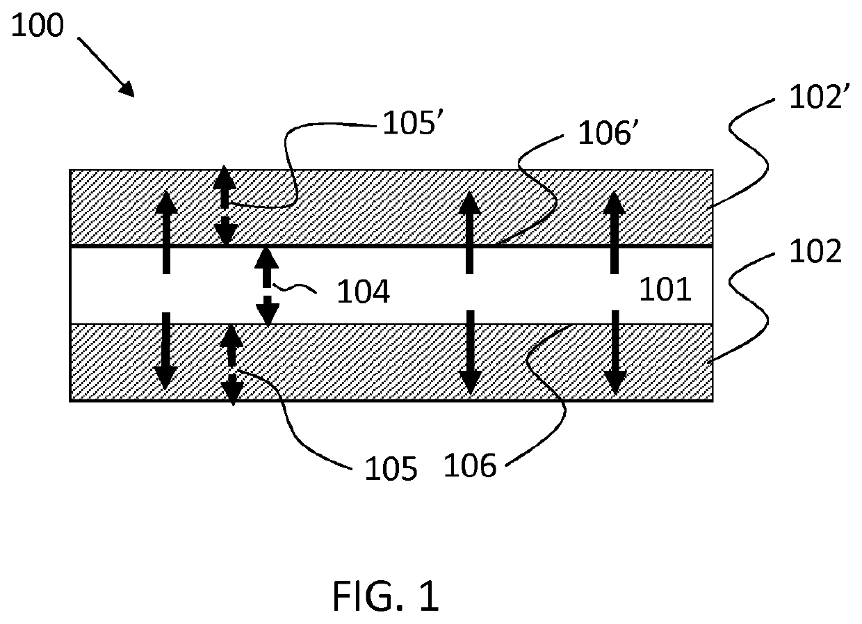
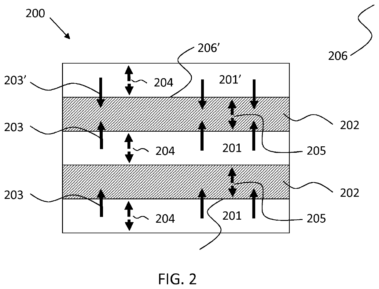
[0042]The claims define an actuator device comprising an actuation structure that can provide actuation based on the presence of a photoresponsive portion which, when it receives actuation light, can deform and a light guiding layer, i.e. a light guide for guiding and providing the actuation light to the photoresponsive layer. The actuation structure is constructed such that the photoresponsive portion is illuminated more efficiently than a photoresponsive portion of the same volume and incorporated in an actuation structure. Hence, an improved actuation output (stroke and / or strain) can be obtained with a particular volume of photoresponsive portion.

[0043]Whilst the layers closer to the light source will deform more than those further away due to attenuation of the light as it passes through progressively more layers, deformable non-photoresponsive layers (light guiding layers) are provided which partition adjacent photoresponsive layers. They guide unabsorbed light between the lay...


PUM

PropertyMeasurementUnit
thicknessaaaaaaaaaa
thicknessesaaaaaaaaaa

Abstract

An actuator device comprises a stack formed from a plurality of photoresponsive layers, which deform in response to light, which are partitioned by respective deformable non-photoresponsive layers. The deformable non-photoresponsive layers guide light between and to the photoresponsive layers, and can follow the deformation of the photoresponsive layers.

Description

CROSS-REFERENCE TO PRIOR APPLICATIONS[0001]This application is the U.S. National Phase application under 35 U.S.C. § 371 of International Application No. PCT / EP2017 / 073388, filed on Sep. 18, 2017, which claims the benefit of EP Patent Application No. EP 16189915.8, filed on Sep. 21, 2016 and EP Patent Application No. EP 17158318.0, filed on Feb. 28, 2017. These applications are hereby incorporated by reference herein.FIELD OF THE INVENTION[0002]This invention relates to a device with an actuator that can be actuated by light. The invention also relates to an actuation method and manufacturing method.BACKGROUND OF THE INVENTION[0003]Electroactive materials, which turn electrical energy into mechanical action, have been investigated for a number of applications. However, such materials can require relatively high voltages which can discourage their use in some applications such as in devices to be used in or near the body. Catheter steering and ‘soft robotics’ (e.g. garments that help...

Claims


Application Information

Patent Timeline
Patent Type & Authority Patents(United States)
IPC IPC(8): C09K19/38B32B27/08C09K19/54B29C70/00C09K19/24C09K19/20B32B7/023F03G7/00F03G7/06H02N11/00C09K19/04C09K19/34
CPCC09K19/3852B29C70/00B32B7/023B32B27/08C09K19/2007C09K19/24C09K19/3804C09K19/3833C09K19/542F03G7/005F03G7/06H02N11/006B32B2307/40C09K2019/0425C09K2019/0437C09K2019/0448C09K2019/2035C09K2019/2078C09K2019/3425C09K2219/00F03G7/009F03G7/016F03G7/0613
Inventor LUB, JOHANWILLARD, NICOLAAS PETRUSHENDRIKS, CORNELIS PETRUSVAN DEN AKER, KAREL JOHANNES ADRIANUS
Owner KONINKLJIJKE PHILIPS NV
Why Eureka
Try Eureka