Imaging spectropolarimeter using orthogonal polarization pairs

a spectropolarimeter and orthogonal polarization technology, applied in the direction of interferometric spectrometry, optical radiation measurement, instruments, etc., can solve the problems of inefficient arrangement in terms of photon collection efficiency, increased complexity, and increased complexity, so as to avoid additional signal loss at the system input.

Active Publication Date: 2015-11-10
RAYTHEON CO
View PDF5 Cites 0 Cited by
  • Summary
  • Abstract
  • Description
  • Claims
  • Application Information

AI Technical Summary

Benefits of technology

[0007]Aspects and embodiments are directed to a high extinction spectropolarimeter capable of providing simultaneous measurements of orthogonal polarization pairs. Additionally, as discussed in more detail below, the polarimetry function is implemented “within” the spectrometer, rather than using a polarizing filter placed at the input to the system (as is sometimes done conventionally), thereby avoiding any additional signal loss at the system input.

Problems solved by technology

This configuration avoids the 50% radiation loss associated with the configuration of FIG. 1A, but is more complex and requires additional components.
Thus, this arrangement is very inefficient in terms of photon collection efficiency and is susceptible to errors if the object or scene being measured undergoes changes while the inserted polarizer is switched.
Conventional imaging polarimeters (that perform polarimetry alone and are not capable of spectral imaging) use quadrant wire grids positioned over the focal plane array separate the polarizations incident on each pixel of the focal plane array.
However, as may be seen with reference to FIG. 2, with this arrangement, the distance between like polarizations is too great to enable perfect interpolation.
In addition, signal leakage occurs between pixels which further degrade the image quality.

Method used


Image

  • Imaging spectropolarimeter using orthogonal polarization pairs
  • Imaging spectropolarimeter using orthogonal polarization pairs
  • Imaging spectropolarimeter using orthogonal polarization pairs

Examples


Embodiment Construction

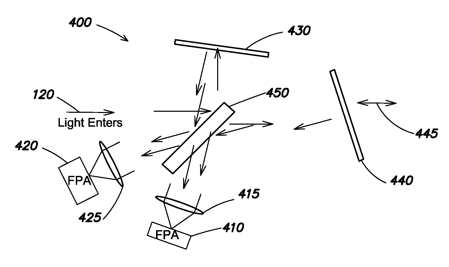
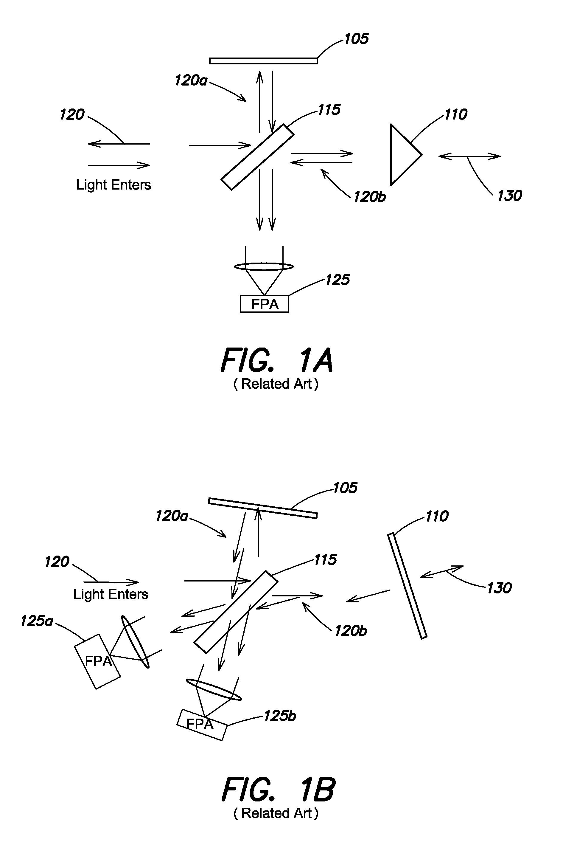
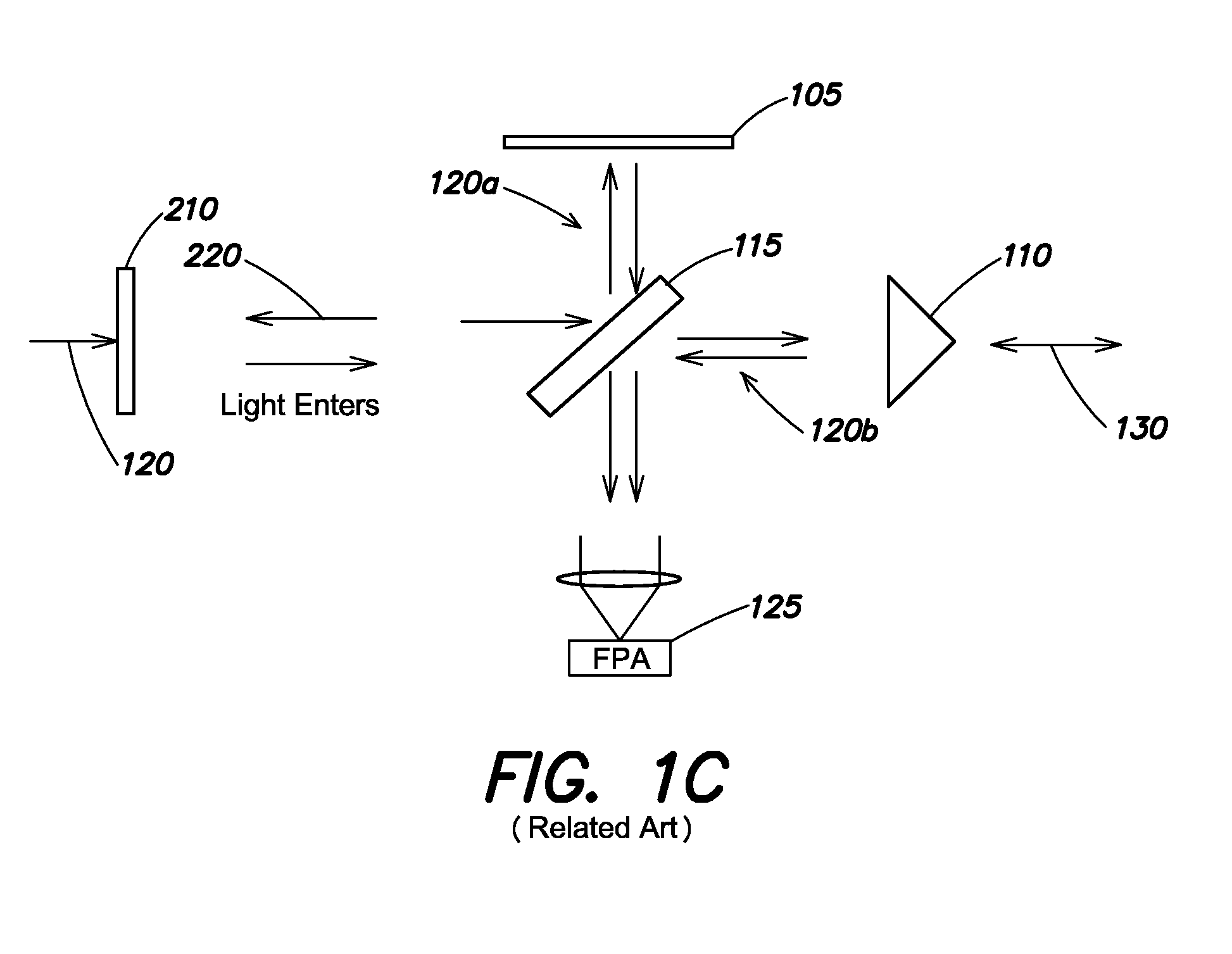
[0030]A sensor combining imaging spectrometry and polarimetry may provide powerful dual (orthogonal) phenomenologies to detect targets and reduce or eliminate false alarms. However, conventional spectropolarimeters suffer from issues with sensitivity and simultaneity when dividing the incoming signal into different wavebands and polarizations. As discussed above, conventional spectropolarimeters have low efficiency as there are very few photons per spectral channel per polarization, which can result in focal plane noise dominating the overall signal to noise ratio of retrieved spectra. For example, a system such as that illustrated in FIG. 2 loses 50% of the input signal even when performing spectral imaging alone, and when modified to collect spectra and polarization data simultaneously (with the insertion of the polarizer 210 in the input optical train) loses 75% of the signal at any time. Additionally, conventional spectropolarimeters measure different polarizations sequentially ...


PUM


Abstract

An imaging interferometric transform spectropolarimeter configured to simultaneously collect four polarizations. In one example, an spectropolarimeter includes a dual-beam interferometric transform spectrometer configured to receive electromagnetic radiation from a viewed scene, and including first and second focal plane arrays that are spatially registered with one another, a first polarizer coupled to the first focal plane array and configured to transmit only a first pair of polarizations to the first focal plane array, and a second polarizer coupled to the second focal plane array and configured to transmit only a second pair of polarizations to the second focal plane array, the second pair of polarizations being different than the first pair of polarizations.

Description

BACKGROUND[0001]Imaging spectroscopy is widely used in remote sensing applications. Polarimetry, or measurement of polarized electromagnetic radiation, may also provide useful information about an object, and typically provides at least some different information than is obtained by spectral imaging. In particular, polarimetry is sensitive to the object orientation, composition, and surface roughness, whereas, spectral information is primarily related to material composition. Therefore, in certain applications, it may be desirable to perform both spectral imaging and polarimetry. Generally, this is achieved using two separate instruments, namely, a polarimeter and an imaging spectrometer, although there have been some attempts to combine the two functions into a single instrument.[0002]One type of interferometric spectrometer used to supply spectral data for many remote sensing applications is called a Fourier Transform Spectrometer (FTS). A common form of an FTS employs a Michelson...

Claims


Application Information

Patent Timeline
Patent Type & Authority Patents(United States)
IPC IPC(8): G01J3/45G01J3/453G01J3/28G01J3/02G01J3/12
CPCG01J3/2823G01J3/0224G01J3/4531G01J2003/1291G01J3/45G01J4/04G01J2003/2826
Inventor ROBINSON, IAN S.BLOOMER, JOHN D.
Owner RAYTHEON CO
Why Eureka
Try Eureka