[0008]In view of the foregoing, it is an object of the invention to provide a
system and method using multistage force amplification of piezoelectric
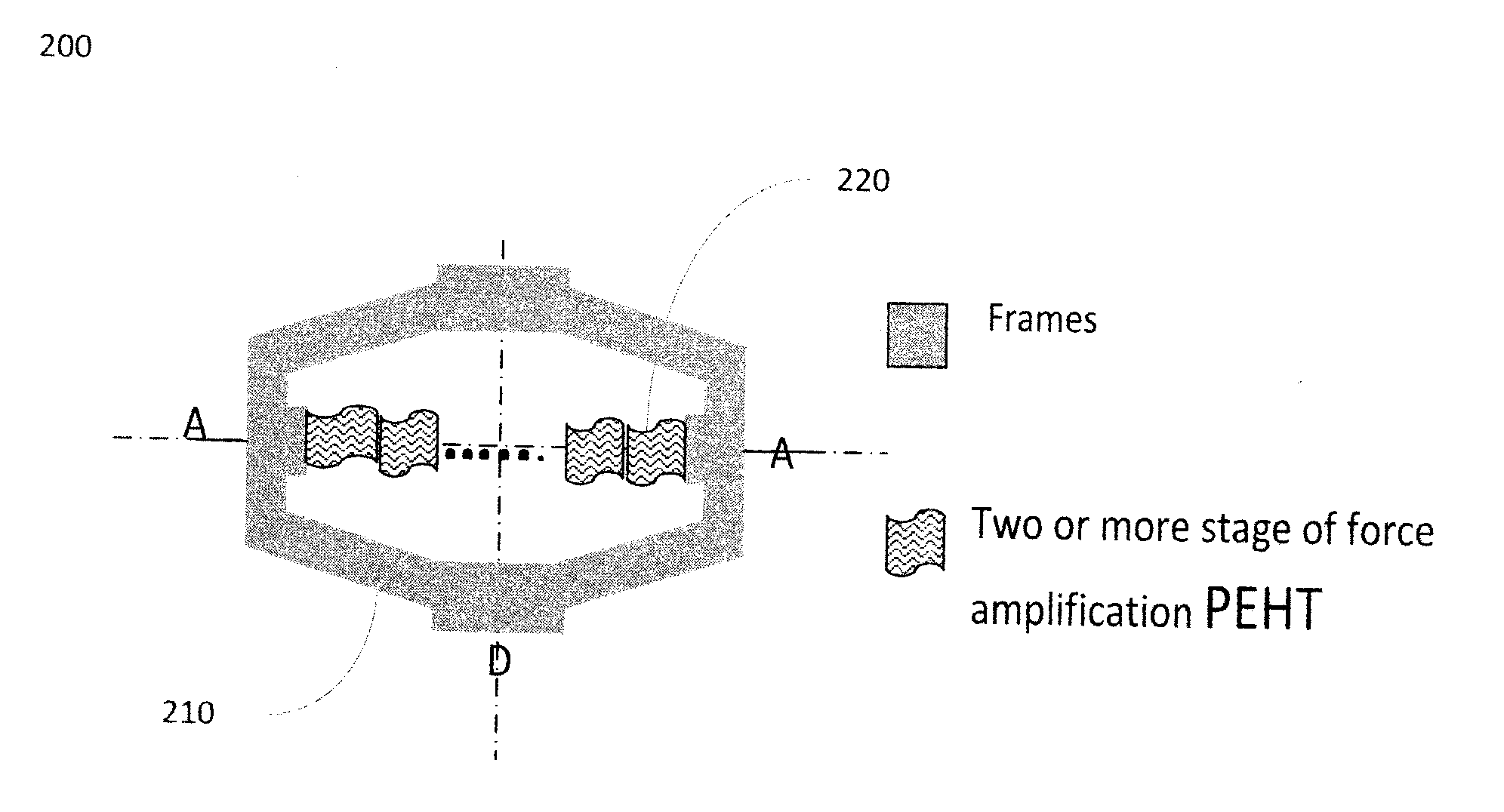
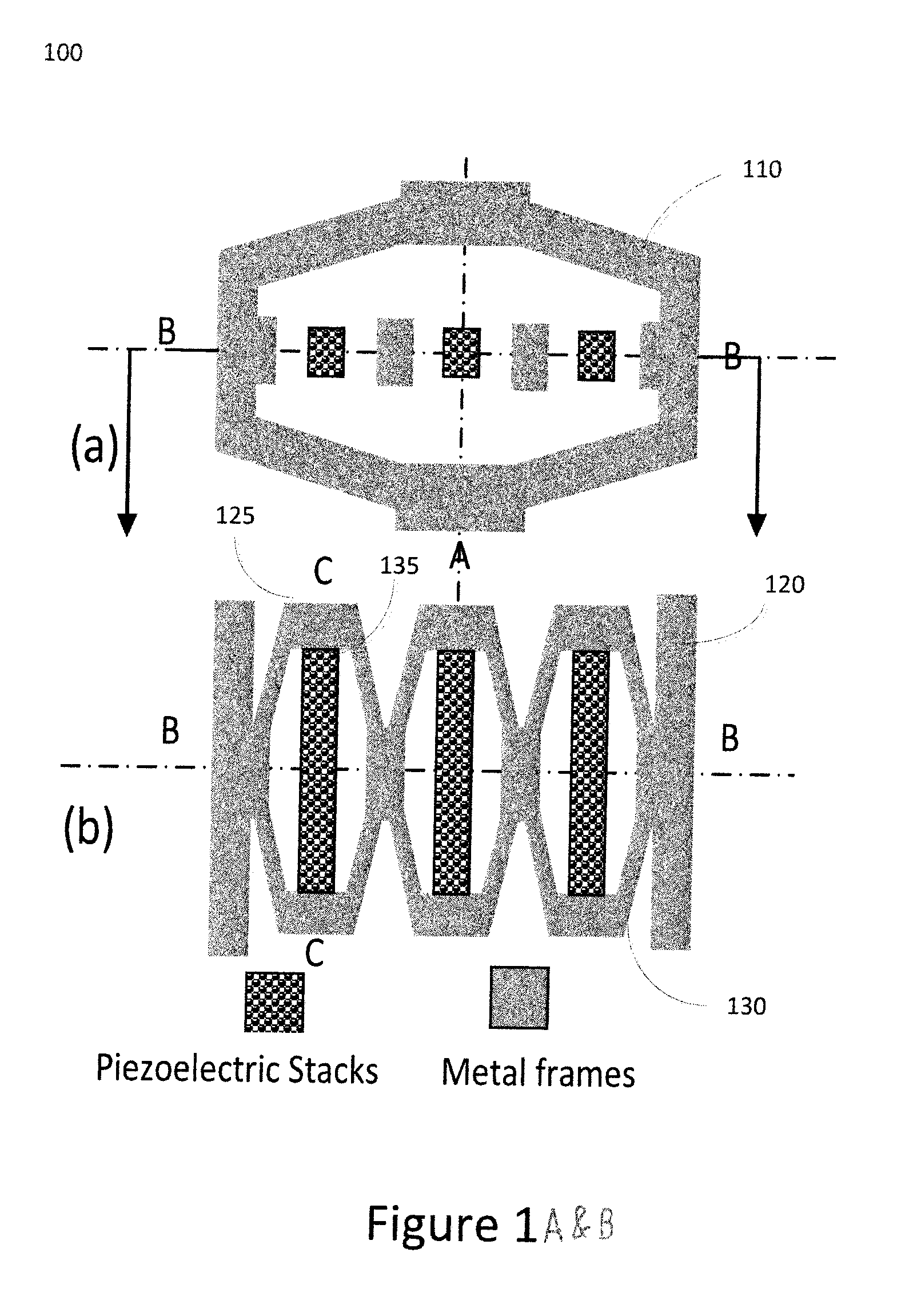
energy harvesting transducers (MFAPEHTs). In this MFAPEHT, a multistage force amplification mechanism is employed to increase the effective
piezoelectric constant and optimize the
mechanical impedance match in order to increase
mechanical energy input to the device with same
mechanical vibration source. Aspects of MFAPEHTs may include a configuration that enables to amplify the input
mechanical vibration force to more than one order of amplitude to apply every layer of the piezoelectric multilayer stacks. Further, a MFAPEHT can reduce the input stiffness of the PEHT to match the
mechanical impedance of a
mechanical vibration media and to increase the
mechanical energy absorption from environments. In addition, the MFAPEHT structure can increase the effective
piezoelectric constant in order of amplitudes. Moreover, the force amplification mechanism of the MFAPEHT may not affect the overall
capacitance. Also, experimental data shows that the harvested
electric power is proportional to the square of the amplitude of the force amplification when piezoelectric material working in
linear range. Further, no share force is applied to the piezoelectric multilayer stack and compress stress is dominated in the MFAPEHT. Therefore, the MFAPEHT may have higher reliability and broad range of working stresses. Further, the same-sized MFAPEHT compared to a conventional PEHT, the MFAPEHT is capable to harvest
electric power more than order of higher than a conventional PEHT. Also, the MFAPEHT can be used broadly for portable electronic devices for military and civilian applications such as aircraft, automobile and other transportation equipment to harvest waste
mechanical energy and reduces
noise.
[0009]In another embodiment of a MFAPEHT, relaxor piezoelectric
single crystal multilayer stacks for
energy harvesting transducers (RPSEHT), can also provide significant improvements over the current state of the art. Research developments have demonstrated that PMN-PT and PZN-PT relaxor
single crystal materials have high piezoelectric constants (d33>1500 pC / N) and high
electromechanical coupling factors (k33>88%) as well as advantageous cryogenic properties. Further, RPSEHT is capable of converting more than 50% of mechanical energy input into electrical energy out using relaxor piezoelectric
single crystal materials, which possess greater than 80% mechanical-electrical
coupling factors. In addition, the RPSEHT remains
high energy conversion efficiency, i.e., high mechanical-electrical
coupling factor, in a broad range of temperatures (from 70 C to at or near cryogenic temperatures). Moreover, the RPSEHT enable harvesting energy with high efficiency in both of off-
resonance mode a
resonance mode in a broad range of frequencies. Also, the RPSEHT structure increases the effective
piezoelectric constant by an
order of magnitude comparing with that of its piezo
ceramic counterpart. The RPSEHT can harvest more electric charges compared to a single layer bulk relaxor piezoelectric single
crystal of the same size given the same applied vibration motion force due to the high effective piezoelectric constraint of the RPSEHT. Further, the RPSEHT structure can increase the
capacitance by
order of magnitude such that it can translate into an increase in the
energy storage capability and a reduction of magnitude in
voltage. In addition, the RPSEHT structure can be scaled to any size and integrated into a vibration /
motion system. Moreover, RPSEHT structure is more reliable and durable for applications in dynamic systems as well as portable electronic devices in military and civilian applications such as aircraft, automobiles, and other vehicles to harvest waste mechanical energy. Also, the RPSEHT may enable to reduce harmful vibration /
noise significantly in various ranges of frequencies and temperature environments when applied.
[0010]In order to enhance the mechanical energy output to obtain high displacement, large
mechanical load capability (high blocking force) and high displacement height ration with low applied
voltage for
actuator transducer, a secondary amplification of multiple flextensional actuations
system (SAMFATS) is disclosed. The SAMFATS can provide several times larger displacement than a similarly sized flextensional
actuator /
transducer with the same level of
mechanical load capability. Further, the SAMFATS has strong
resonance for
transducer applications. Moreover, the SAMFATS provides extremely high effective piezoelectric constant at resonance frequency and off-resonance frequencies. The effective piezoelectric constant can be controlled by varying the size of each component, the degree of the precurvature of the frames, the thickness of each layer in the multilayer stacks, and the piezoelectric materials used. In addition, the SAMFATS can offer high displacement height ratio (or effective device strain) as well as work in a broad temperature range (from
Liquid nitrogen temperature to >100 C), and preferably in at least some embodiments at or near cryogenic conditions. Further, the performance of SAMFATS can always be improved by enhancing the piezoelectric material properties. In addition, a SAMFATS device enables future
actuator designs and expands piezoelectric material applications.
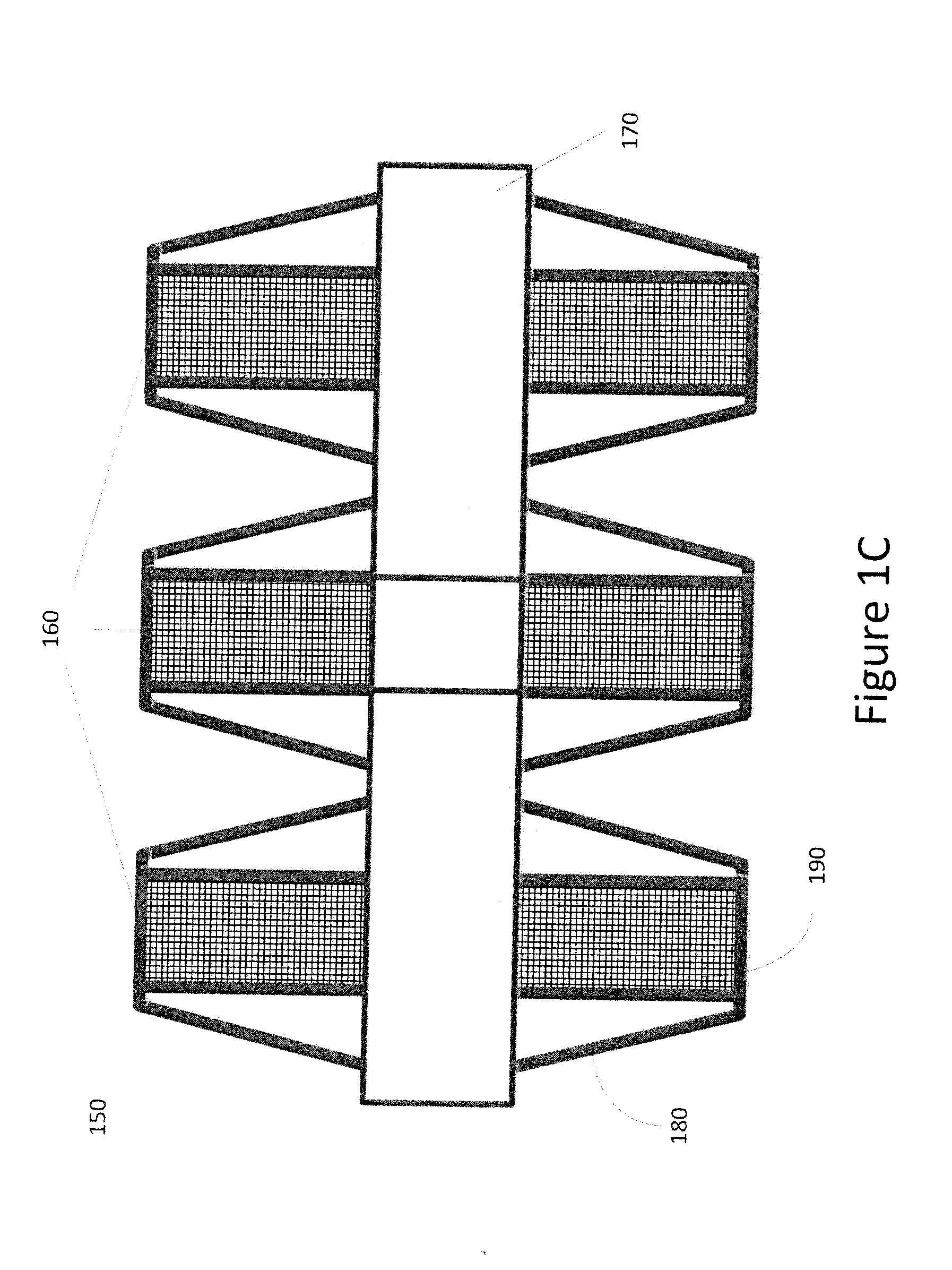
[0013]Embodiments of the disclosure may also include methods for using a piezoelectric device, the method including steps for providing outer flextensional casing and a first cell and a last cell of a transducer coupled to the outer flextensional casing, each cell having a flextensional
cell structure that includes a piezoelectric stack coupled to each flextensional
cell structure of each cell. Such a method may also include receiving an input force at the first cell, amplifying the input force at the first cell to provide an output force for the first cell, receiving the output force of the first cell as the input force of the last cell, and amplifying the input force at the last cell to provide an output force for the last cell. Further, a first transducer output force is product of the input force of the first cell, the output force of the first cell, and the output force of the last cell. Additional steps in the method may include providing piezoelectric energy from the piezoelectric stack of each flextensional cell structure of each
cell based on first transducer output force as well as providing
displacement based on the first output transducer force. Further steps may include receiving the input force along a first axis at each flextensional cell structure and providing the output force along a second axis that is amplified compared to the first input force as well as reducing the stiffness of the transducer thereby increasing the amplification of the each input force for each cell and applying a
voltage to each piezoelectric stack.

