
Spinal rod link reducer

a technology of reducer and rod link, which is applied in the field of bone fixation, can solve the problems of long operation time, unsatisfactory conventional correction methods, and vcr-posterior vertebral column resection, and achieve the effects of stabilizing the spine, safely translating the spine, and effectively derotating the spin

Active Publication Date: 2016-08-09
GLOBUS MEDICAL INC
View PDF112 Cites 14 Cited by
  • Summary
  • Abstract
  • Description
  • Claims
  • Application Information

AI Technical Summary

Benefits of technology

The system provides better spinal stability, more reliable deformity correction, and shorter surgical times by allowing controlled derotation and translation of the spine, reducing the risk of spinal cord injuries and enabling more extensive correction in a single procedure.

Problems solved by technology

However, the conventional correction methods, such as posterior correction only or anterior release and posterior instrumentation, are usually unsatisfactory.
However, the anterior-posterior vertebral column resection (VCR) has disadvantages such as long operative time, potential significant blood loss, and risk of intraoperative neurologic impairment due to the spinal column segment instability during the resection and the correction procedure.
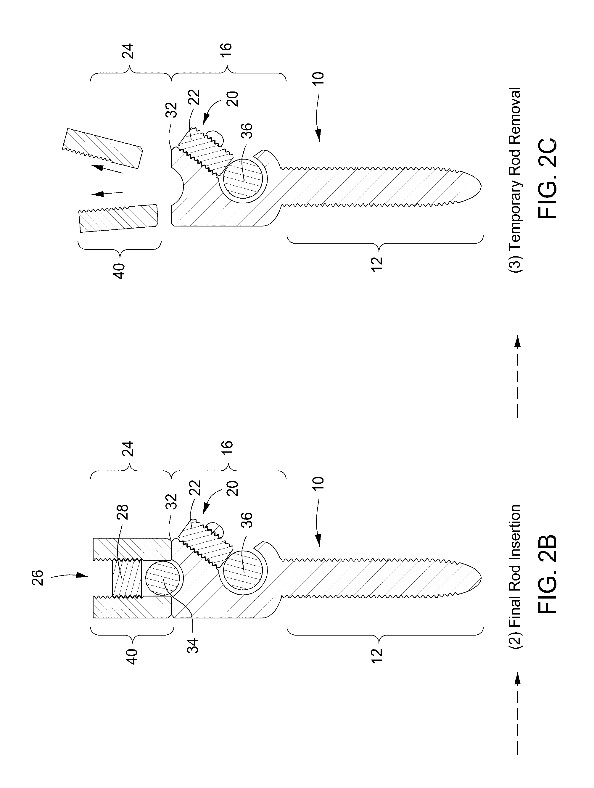
However, these technique have a number of disadvantages: 1) the risk of intraoperative mishaps due to the instability resulting from exchanging the temporary rods may produce spinal cord injury; 2) limitation in deformity correction secondary to a “one-time” correction maneuver utilized using the Suk technique; 3) short segment fixation using the provisional rods since multiple exchanges prevent long rod utilization; and 4) additional surgical time necessary with multiple removal and insertion of the temporary provisional rods.

Method used


Image

  • Spinal rod link reducer
  • Spinal rod link reducer
  • Spinal rod link reducer

Examples


Embodiment Construction

[0051]While the making and using of various embodiments of the present invention are discussed in detail below, it should be appreciated that the present invention provides many applicable inventive concepts that can be embodied in a wide variety of specific contexts. The specific embodiments discussed herein are merely illustrative of specific ways to make and use the invention and do not delimit the scope of the invention.

[0052]To facilitate the understanding of this invention, a number of terms are defined below. Terms defined herein have meanings as commonly understood by a person of ordinary skill in the areas relevant to the present invention. Terms such as “a”, “an” and “the” are not intended to refer to only a singular entity, but include the general class of which a specific example may be used for illustration. The terminology herein is used to describe specific embodiments of the invention, but their usage does not delimit the invention, except as outlined in the claims.

[...


PUM


Abstract

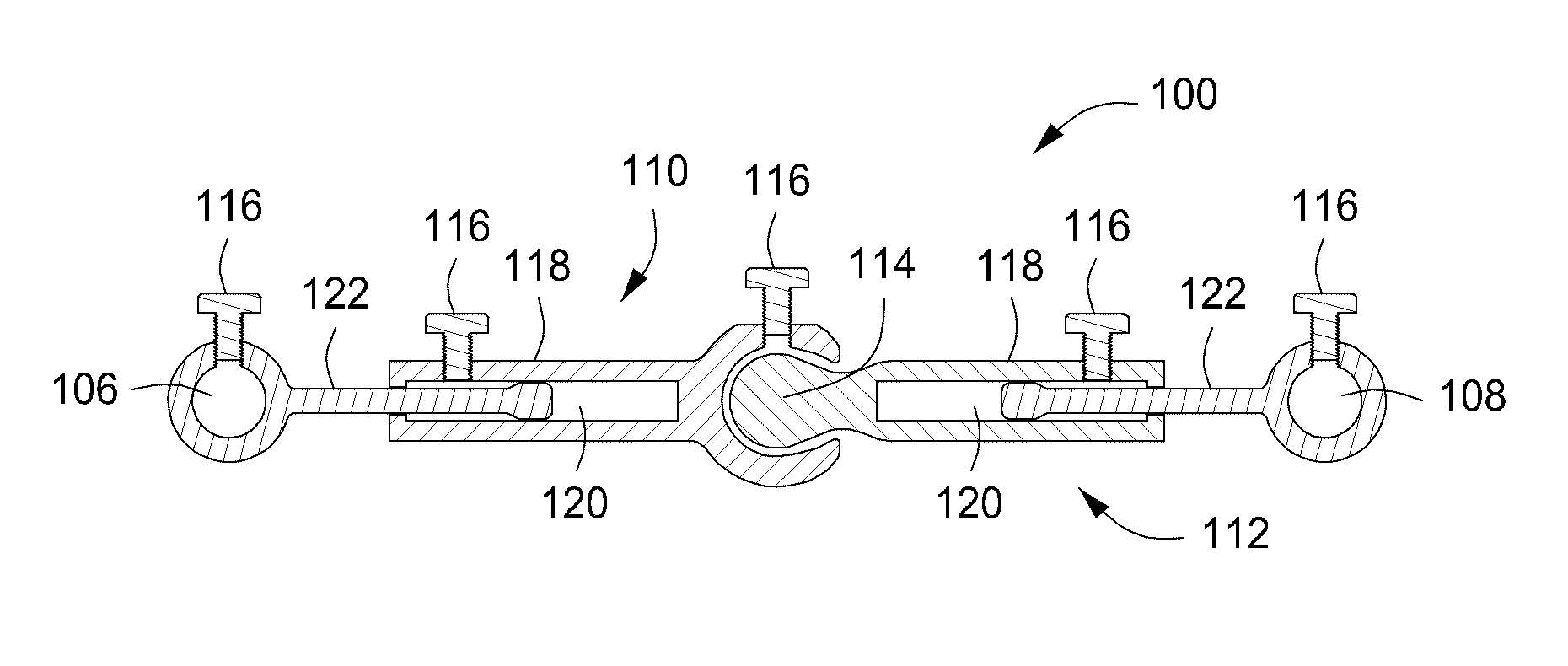
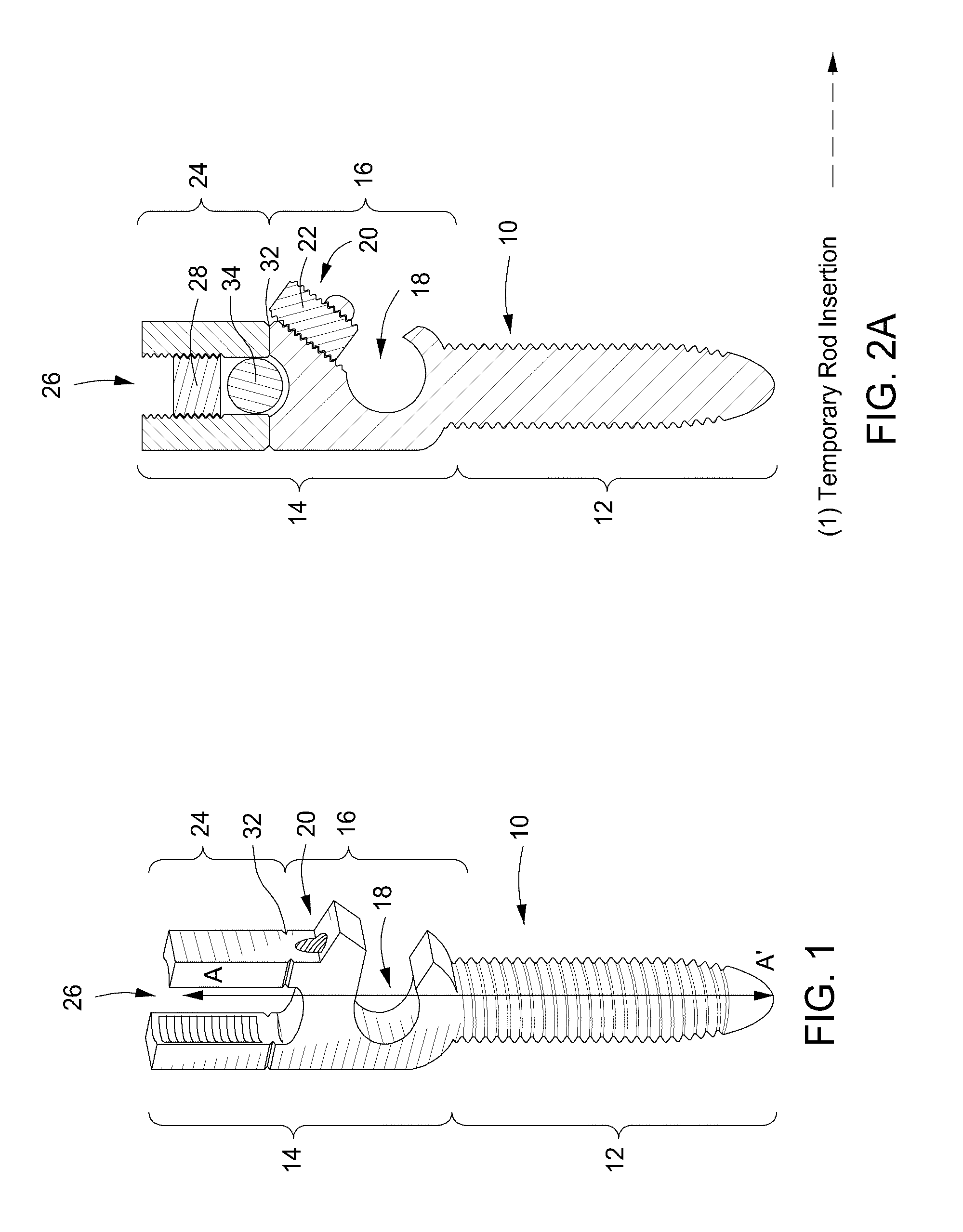
The present invention includes a rod link reducer of a spinal fixation system that includes a first and a second spinal rod manipulator; a first spinal rod manipulator joint connected to the first spinal rod manipulator and a second spinal rod manipulator joint connected to the second spinal rod manipulator; a first and a second translatable transverse shaft connected to the first and second joints, respectively; and a universal reducer connected to both the first and second translatable transverse shafts, wherein the universal reducer, the shafts and the linkers provide movement and temporary fixation of a spine that has been manipulated into a final position during spinal surgery.

Description

CROSS-REFERENCE TO RELATED APPLICATIONS[0001]This application claims priority to U.S. Provisional Application Ser. No. 61 / 025,761, filed Feb. 2, 2008, and to U.S. Provisional Application Ser. No. 61 / 080,162 filed Jul. 11, 2008, the contents of both of which is incorporated by reference herein in its entirety.TECHNICAL FIELD OF THE INVENTION[0002]The present invention relates in general to the field of bone fixation, and more particularly, to a novel rod link reducer for use during the correction of mild to severe spinal deformities.STATEMENT OF FEDERALLY FUNDED RESEARCH[0003]None.BACKGROUND OF THE INVENTION[0004]Without limiting the scope of the invention, its background is described in connection with pedicle screws.[0005]In rigid severe spine deformity with coronal or sagittal decompensation, translation of the spinal column is necessary for restoration of trunk balance as well as deformity correction. However, the conventional correction methods, such as posterior correction only...

Claims


Application Information

Patent Timeline
Patent Type & Authority Patents(United States)
IPC IPC(8): A61B17/70
CPCA61B17/7023A61B17/7034A61B17/705A61B17/7052A61B17/7086A61B17/7079A61B17/7011A61B2090/037
Inventor ZHANG, HONGSUCATO, DAN
Owner GLOBUS MEDICAL INC
Learn More