
CG height adjustability by conformal crown weighting

a crown weighting and height adjustment technology, applied in the field of golf club head conformal weight placement, can solve the problems of reducing overall performance, difficult to achieve sufficient center of gravity range, and relatively little done with the placement of adjustable weights directly in the crown of drivers, so as to minimize the effect of appearance or no effect at address, maximizing the ability of weight, and minimizing any potential impact sound

Active Publication Date: 2016-08-09
TOPGOLF CALLAWAY BRANDS CORP
View PDF5 Cites 13 Cited by
  • Summary
  • Abstract
  • Description
  • Claims
  • Application Information

AI Technical Summary

Benefits of technology

The technical effect of this patent is to provide a way to adjust the weight of a device's center of gravity while minimizing the impact on its appearance and sound. This can be done by adding or removing interchangeable parts that affect the device's weight, or by adjusting the placement of a fixed weight. The goal is to make the device more effective and efficient in performing its intended function. Additionally, the patent describes how to create a discreet or fully concealed weight system that can still be controlled to adjust the center of gravity.

Problems solved by technology

Relatively little has been done with the placement of adjustable weights directly in the crowns of drivers.
Unfortunately, achieving sufficient center of gravity range is difficult, such installations are visually distracting at address, the fixed structure of a weight port is inefficient and penalizes overall performance, and a concentrated mass located in the center of the crown can have an adverse effect on impact sound.
Unfortunately, this adds to the fixed portion of the adjustable weighting system mass and further detracts from its efficiency.
The cover can also become a source of buzzing or can become detached and possibly lost.
Both of these approaches add to the fixed structural weight of the crown and tend to increase the center of gravity height.
Weight ports in the crown that are visible at address are not desirable.
They are potentially distracting and can impact cosmetic appearance.
In addition, the weight port structure adds to total crown mass.

Method used


Image

  • CG height adjustability by conformal crown weighting
  • CG height adjustability by conformal crown weighting
  • CG height adjustability by conformal crown weighting

Examples


Embodiment Construction

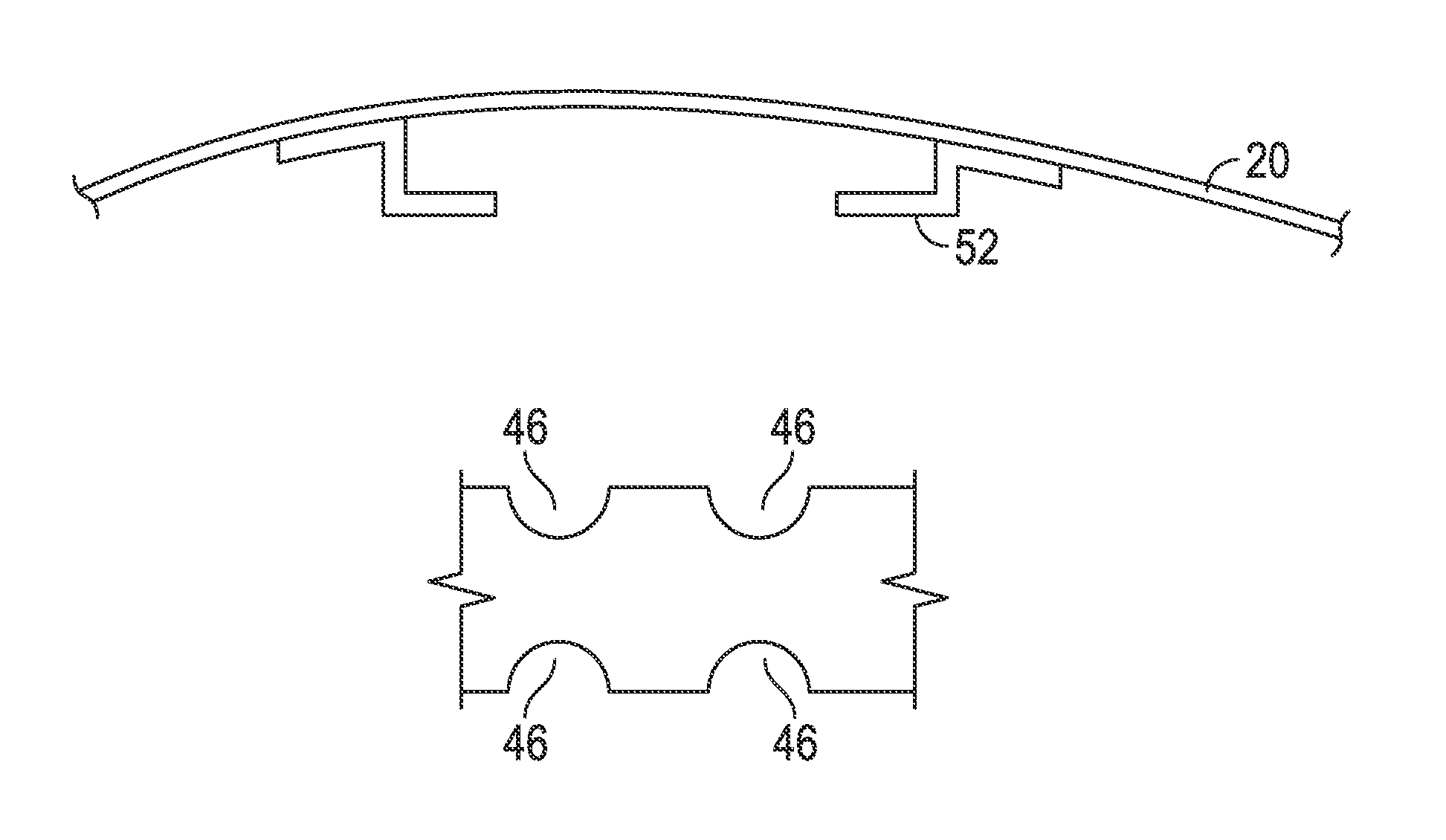
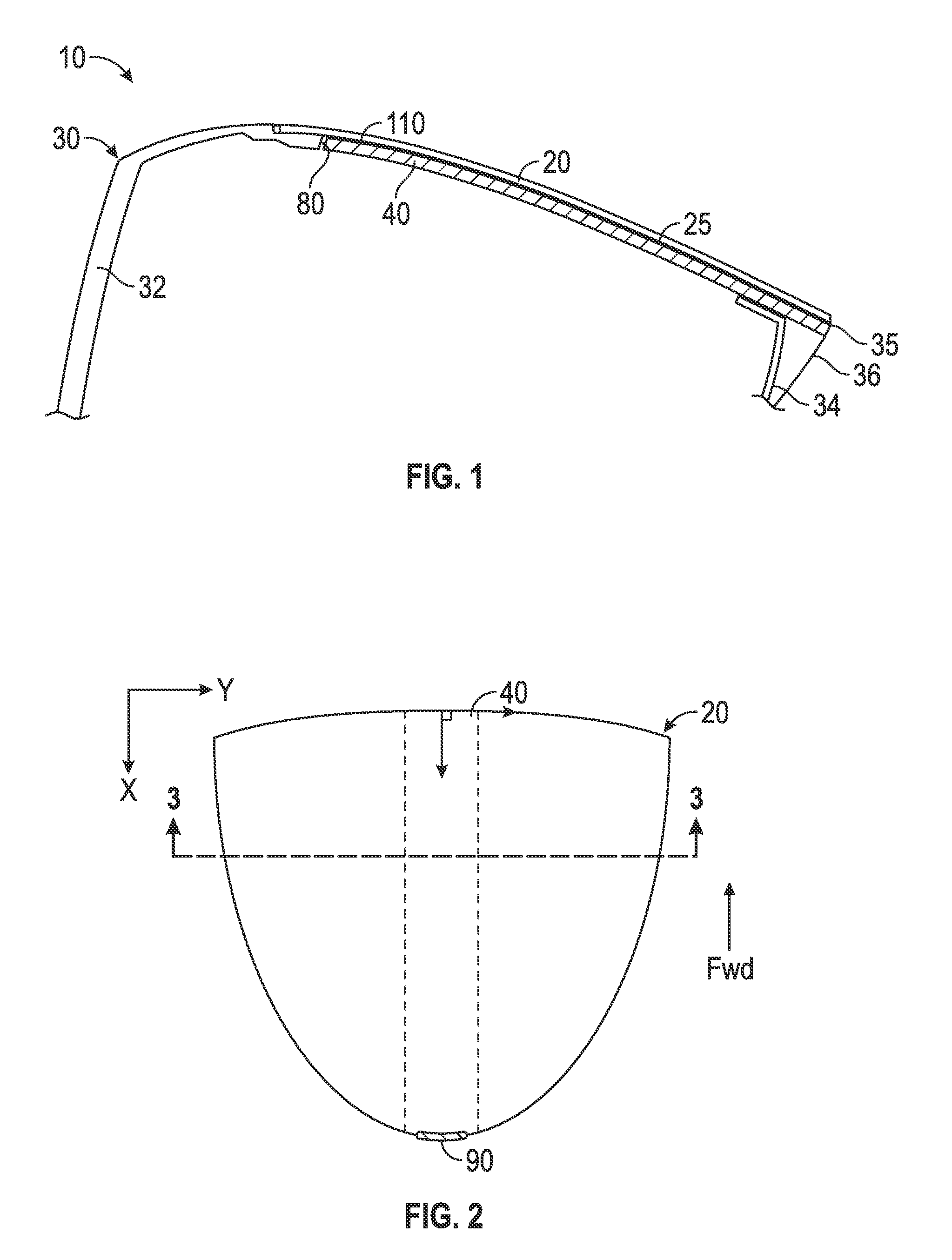
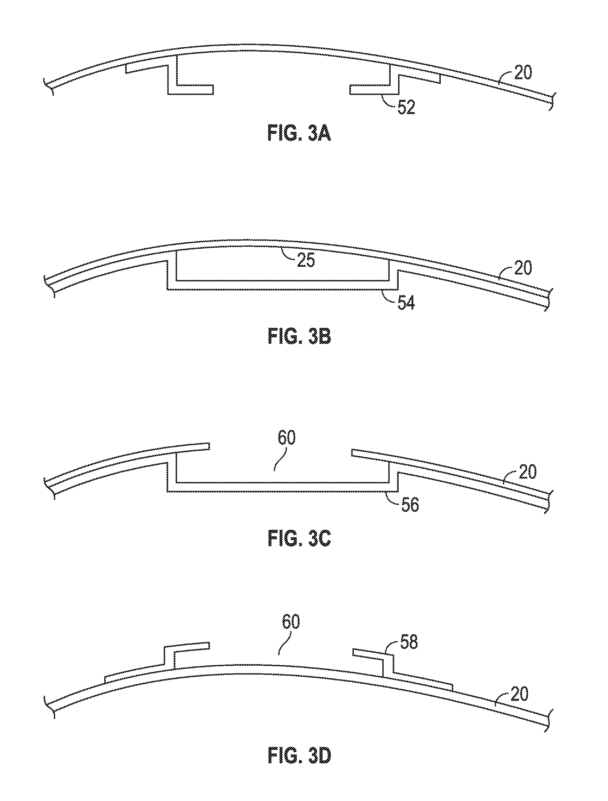
[0026]As shown in FIG. 1, the design approach described here is based on the construction used in Callaway Golf Company's RAZR Fit driver head 10, characterized by a composite crown 20 adhesively bonded to a cast Titanium body 30, which comprises a face 32, a sole 34, and sometimes a ribbon 36. This particular construction approach permits the crown 20 configuration to be adapted to the hidden conformal weighting system 100 described herein with minimal impact to weight and function. However, this weighting system 100 may be used with other constructions including all Titanium, all composite and composite body with metal face cup. It is also intended to work in conjunction with at least one adjustable weight port on the sole of the driver head 10. Shifting weight between the crown weighting system 100 described herein and a port located on the sole 34 allows for control of center of gravity height. In the most general case the sole 34 weighting technique will be different than the c...


PUM


Abstract

A golf club head comprising a crown with an edge support structure and a flexible, conformal weight sized to fit within the edge support structure is disclosed herein. The edge support structure preferably is disposed on an internal surface of the crown so that the conformal weight is invisible when the golf club head is viewed at address. The conformal weight can be removed to adjust the vertical center of gravity of the club head, and preferably is oriented in a front-to-back direction along the club head's X-axis. The conformal weight preferably is composed of a high-density polymeric material with a specific gravity ranging from 1.8 to 4.2.

Description

CROSS REFERENCES TO RELATED APPLICATIONS[0001]The present application is a continuation of U.S. patent application Ser. No. 14 / 151,148, filed on Jan. 9, 2014, and issued on May 5, 2015, as U.S. Pat. No. 9,022,881, which is a continuation-in-part of U.S. patent application Ser. No. 14 / 050,194, filed on Oct. 9, 2013, and issued on Apr. 8, 2014, as U.S. Pat. No. 8,690,708, which is a continuation-in-part of U.S. patent application Ser. No. 13 / 797,404, filed on Mar. 12, 2013, which claims priority to 61 / 657,247, filed on Jun. 8, 2012.STATEMENT REGARDING FEDERALLY SPONSORED RESEARCH OR DEVELOPMENT[0002]Not ApplicableBACKGROUND OF THE INVENTION[0003]1. Field of the Invention[0004]The present invention relates to a golf club head. More specifically, the present invention relates to a conformal weight for a golf club head.[0005]2. Description of the Related Art[0006]Relatively little has been done with the placement of adjustable weights directly in the crowns of drivers. Positioning weight...

Claims


Application Information

Patent Timeline
Patent Type & Authority Patents(United States)
IPC IPC(8): A63B53/06A63B53/04A63B59/00
CPCA63B53/06A63B53/0466A63B60/52A63B2053/0491A63B2209/00A63B2209/02A63B2053/0437A63B2053/0441A63B60/54A63B53/0437A63B53/0441A63B53/045A63B53/0433
Inventor EHLERS, STEVEN M.
Owner TOPGOLF CALLAWAY BRANDS CORP
Learn More