
Apparatus and method for transmitting signal in a wireless communication system

a wireless communication system and antenna technology, applied in diversity/multi-antenna systems, multi-frequency code systems, transmission path sub-channel allocation, etc., can solve the problems of increasing propagation path loss, difficult to secure a broad frequency band in a cellular system operating at or below 5 ghz, and increasing data traffic. , to achieve the effect of reducing the overall system overhead and increasing the antenna gain attributed to beamforming

Active Publication Date: 2016-08-23
SAMSUNG ELECTRONICS CO LTD
View PDF26 Cites 22 Cited by
  • Summary
  • Abstract
  • Description
  • Claims
  • Application Information

AI Technical Summary

Benefits of technology

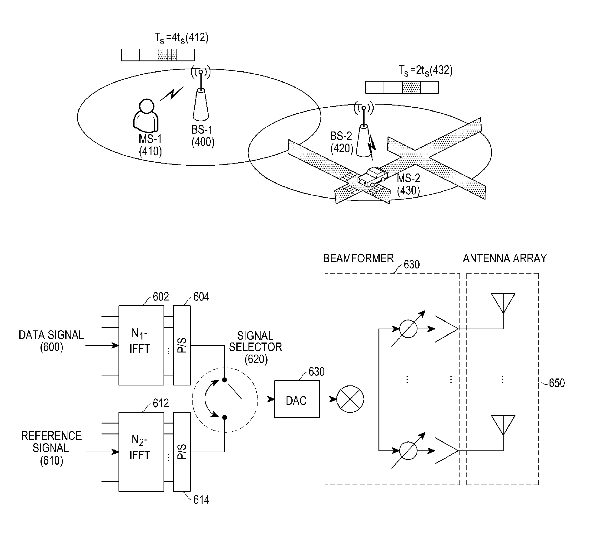
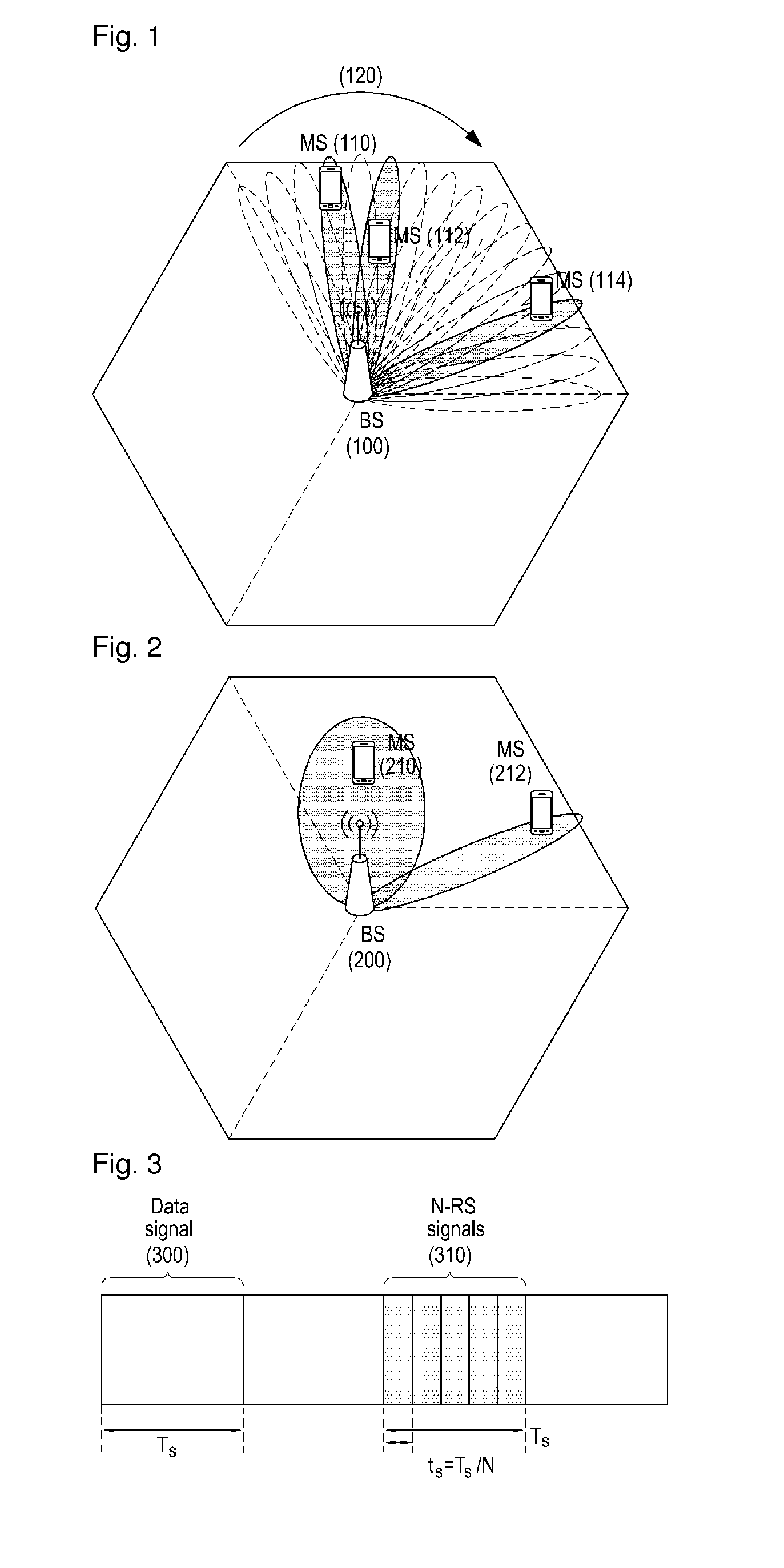
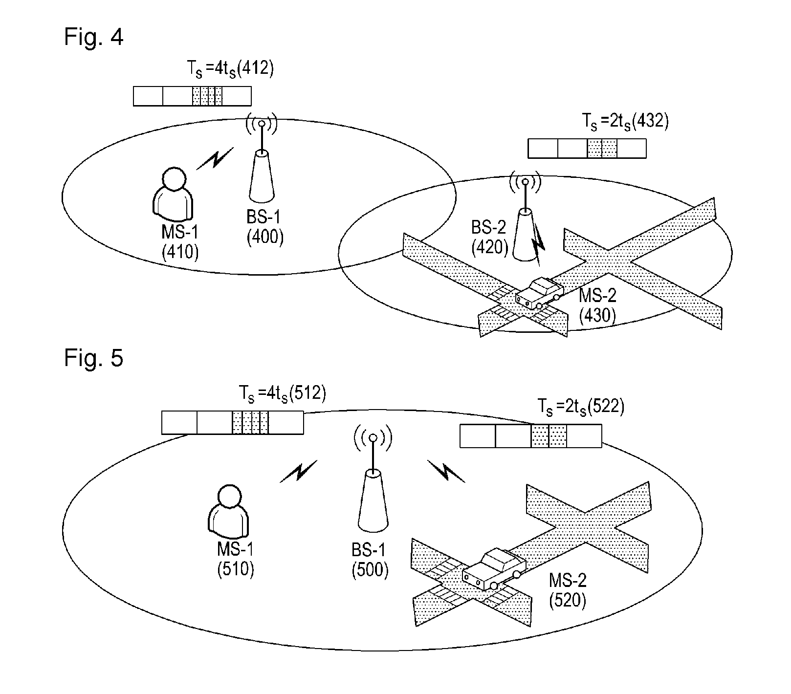
[0028]According to the embodiments of the present invention, the number of reference modulation symbols to be transmitted is adjusted within a data modulation symbol length, taking into account a communication environment. Therefore, an antenna gain attributed to beamforming can be increased and overall system overhead can be reduced.
[0029]Other various effects will be disclosed explicitly or implicitly in the following detailed description of the embodiments of the present invention.

Problems solved by technology

However, it is difficult to satisfy soaring demands for data traffic simply through improved spectral efficiency.
However, it is very difficult to secure a broad frequency band in a cellular system operating at or below 5 GHz, which is a major example of wireless communication systems.
As a higher transmission frequency is used for wireless communication, propagation path loss increases.
The resulting relative short propagation distance leads to reduction of service coverage.
The resulting linear increase in the number of necessary reference signals increases overall system overhead and thus decreases total system capacity.

Method used


Image

  • Apparatus and method for transmitting signal in a wireless communication system
  • Apparatus and method for transmitting signal in a wireless communication system
  • Apparatus and method for transmitting signal in a wireless communication system

Examples


Embodiment Construction

[0039]Reference will be made to preferred embodiments of the present invention with reference to the attached drawings. A detailed description of a generally known function and structure of the present invention will be avoided lest it should obscure the subject matter of the present invention. The terms used in the present invention are defined, taking into account functions in the present invention and may be changed according to the intention of a user or an operator, or customs. Therefore, the present invention must be understood, not simply by the actual terms used but by the meanings of each term lying within.

[0040]In embodiments of the present invention as described later, a frame is configured in such a manner that a transmission apparatus may transmit a data signal and a reference signal according to a specific symbol selection condition in a millimeter wave communication system. To configure the frame, a ‘data signal transmission period’ for transmitting a data signal and ...


PUM


Abstract

An apparatus and method for transmitting a signal needed for beam acquisition in a wireless communication system operating in a super-high frequency band are provided, in which a small reference modulation symbol length relative to a data modulation symbol length is determined, taking into account a communication characteristic of a Mobile Station (MS), a data modulation symbol generated by modulating a data signal using a predetermined modulation scheme is transmitted according to the determined data modulation symbol length, and a reference modulation symbol generated by modulating a reference signal using the predetermined modulation scheme is transmitted according to the determined reference modulation symbol length.

Description

CROSS-REFERENCE TO RELATED APPLICATION(S)[0001]The present application claims priority under 35 U.S.C. §365 to International Patent Application No. PCT / KR2012 / 010991 filed Dec. 17, 2012, entitled “APPARATUS AND METHOD FOR TRANSMITTING SIGNAL IN A WIRELESS COMMUNICATION SYSTEM”. International Patent Application No. PCT / KR2012 / 10991 claims priority under 35 U.S.C. §365 and / or 35 U.S.C. §119(a) to Korean Patent Application No. 10-2011-0136283 filed Dec. 16, 2011 and which are incorporated herein by reference into the present disclosure as if fully set forth herein.TECHNICAL FIELD[0002]The present invention relates to an apparatus and method for transmitting a signal in a wireless communication system, and more particularly, to an apparatus and method for transmitting a signal needed for beam acquisition in a wireless communication system operating in a super-high frequency band.BACKGROUND ART[0003]To satisfy ever-increasing demands for data traffic, wireless communication systems have ...

Claims


Application Information

Patent Timeline
Patent Type & Authority Patents(United States)
IPC IPC(8): H04B15/00H04B7/06H04L27/26H04L5/00H04B7/08
CPCH04L27/2628H04L27/261H04B7/0617H04L5/0023H04L5/0044H04L5/0048H04B7/086H04L27/2634H04L27/26025
Inventor KIM, TAE-YOUNGPARK, JEONG-HOSEOL, JI-YUNYU, HYUN-KYU
Owner SAMSUNG ELECTRONICS CO LTD
Learn More