
Pipe joint gasket and method of making same

a technology of pipe joints and gaskets, which is applied in the direction of pipe joints, fluid pressure sealed joints, sleeve/socket joints, etc., can solve the problems of increasing the tolerances required to form seals, gaskets may fail to form seals between interconnected pipes, etc., to promote effective engagement of singles, increase radially inward force, and promote segmental engagemen

Active Publication Date: 2016-09-06
MCWANE
View PDF15 Cites 5 Cited by
  • Summary
  • Abstract
  • Description
  • Claims
  • Application Information

AI Technical Summary

Benefits of technology

The present invention is a gasket for a pipe joint that ensures the joint remains intact during initial pressurization. This is achieved by promoting the effective engagement of the gasket's teeth with the spigot end of the pipe during pressurization. To improve the likelihood of engagement, the compression arm in each segment is extended radially outward within the gasket to leverage the forces created by the compression of the sealing portion between the spigot end and the bell end. This results in a radially inward force applied by the tooth on the spigot end, thereby improving the engagement of the gasket with the pipe joint.

Problems solved by technology

When this occurs the gasket may fail to form a seal between the interconnected pipe.
Also, when the gasket is positioned improperly between the interconnected pipes the tolerances required to form a seal increase greatly thus, for example, requiring better alignment of the pipes.

Method used


Image

  • Pipe joint gasket and method of making same
  • Pipe joint gasket and method of making same
  • Pipe joint gasket and method of making same

Examples


Embodiment Construction

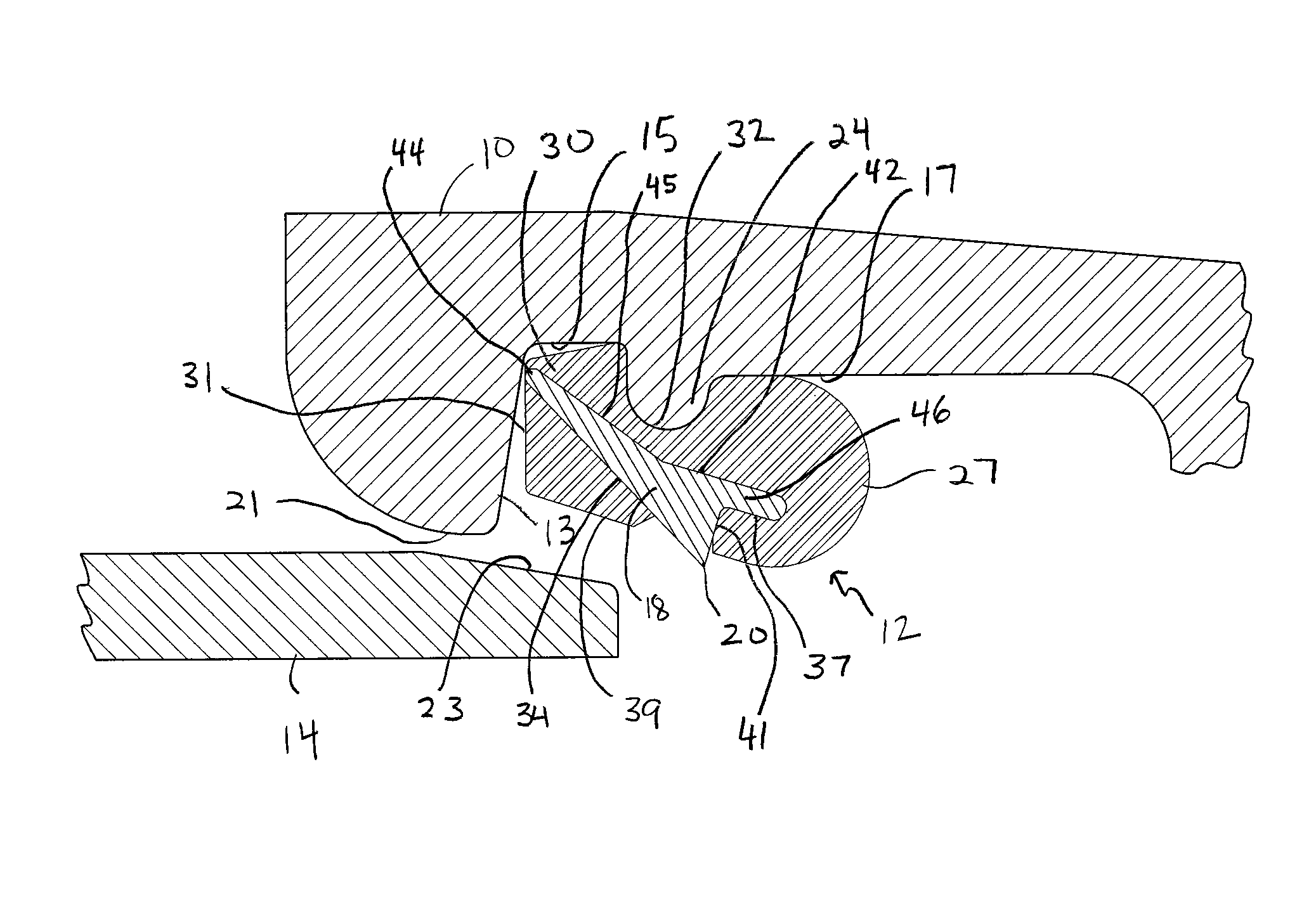
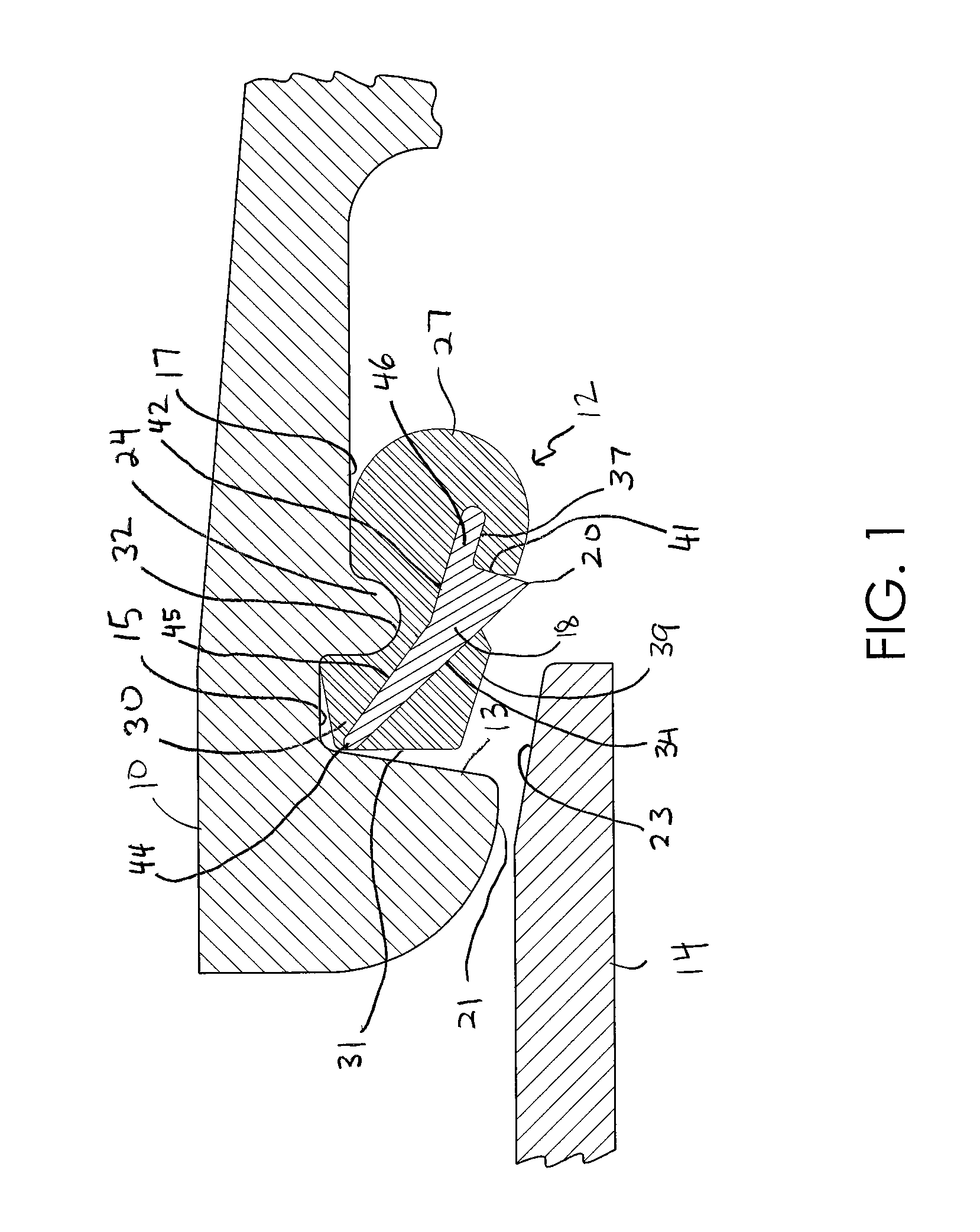
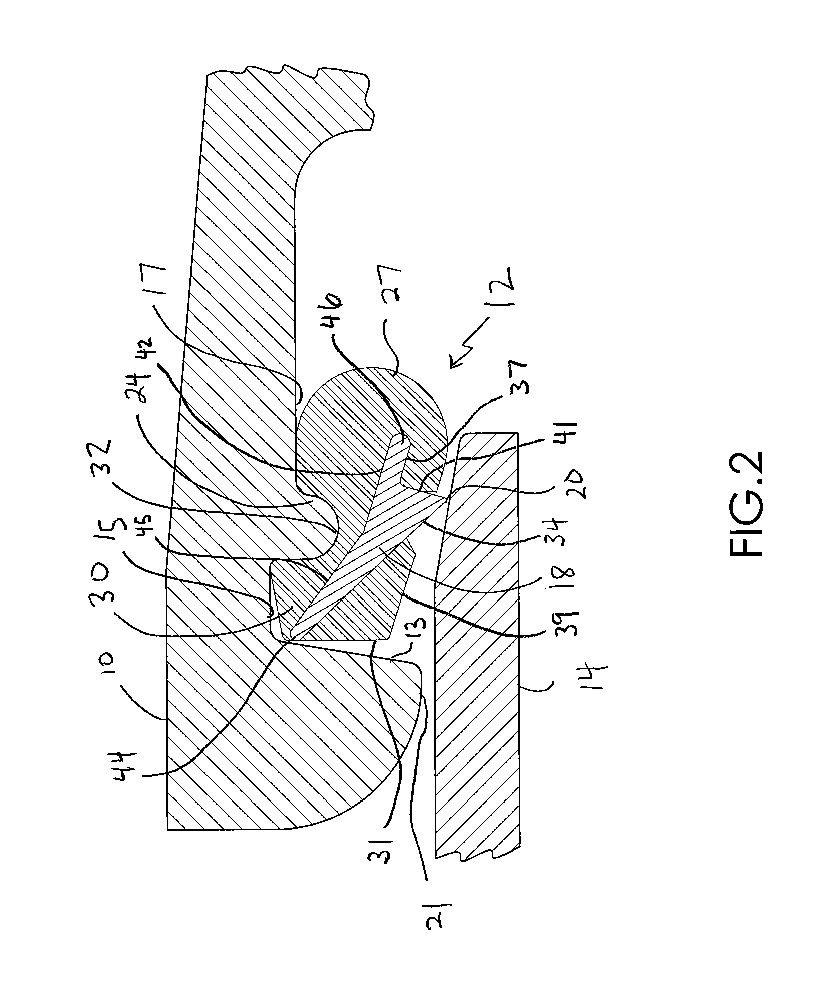
[0011]FIGS. 1 through 4 depict a fragmented cross-sectional view of a bell end 10 of a first pipe, a spigot end 14 of a second pipe entering the pipe bell and the operation of a gasket 12 spaced between the bell end and the spigot end upon entry of the spigot end there through and the fluid pressurization a pipe joint 16 created between bell end 10 and spigot end 14. In particular, these figures illustrate the arrangement and operation of metal segments 18 in gasket 12 relative to bell end 10 and spigot end 14 during the formation and fluid pressurizing of joint 16. FIG. 5 is provided to show the circumferential arrangement and spacing of metal segments 18 throughout gasket 12.

[0012]Generally, gasket 12 is arranged for inhibiting leakage about joint 16 between the inside walls of bell end 10 and the outside wall of spigot end 14. More particularly, as illustrated in FIGS. 1 and 4, the inner surface of bell end 10 includes a retainer groove bounded by a radially extending front wall ...


PUM


Abstract

A pipe gasket including a compressible body having a heel portion and a sealing portion and a plurality of metal segments at least partially embedded in the compressible body and circumferentially spaced therein. Each of the metal segments includes a compression arm extending within the sealing portion and radially outward and away from the heel portion, a rounded nose portion extending within the heel portion and an acutely pointed tooth extending radially inward from a segment portion located between the compression arm and the nose portion. The compression arm extends radially outward within the gasket from a point located proximal to the tip of the tooth to a point within the sealing portion that is distal to the tip of the tooth. This arrangement provides for leveraging of the radial forces created by the compression of the sealing portion between the spigot end and the bell end to increase the radially inward force applied by the tooth on the spigot end.

Description

FIELD OF THE INVENTION[0001]The present invention is directed to a pipe joint gasket and more particularly to a pipe joint gasket including an arrangement of metal segments configured for preventing the separation of interconnected, telescoping pipes during fluid pressurization.BACKGROUND OF THE INVENTION[0002]Pipe joint gaskets including anti-slip segments for preventing the separation of interconnected, telescoping pipes in applications where a fluid such as water for fire mains is held under high pressure are known in the art. Exemplary gaskets are described in U.S. Pat. Nos. 5,295,697 and 5,464,228 in which a rubber gasket, serving as a fluid seal, includes toothed metal segments spaced uniformly around its inner perimeter. The toothed metal segments bite into the outer surface of the spigot of the inserted pipe and prevent withdrawal of the inserted pipe from a bell end of the other pipe. The metal segments pivot about a retainer bead in the bell end of the other pipe to allow ...

Claims


Application Information

Patent Timeline
Patent Type & Authority Patents(United States)
IPC IPC(8): F16L17/06F16L21/02
CPCF16L21/02F16L37/0845
Inventor COPELAND, DANIEL A.
Owner MCWANE
Learn More