Electric vehicle support equipment having a smart plug with a relay control circuit

a technology of relay control circuit and electric vehicle support, which is applied in the direction of relays, electric devices, transportation and packaging, etc., can solve the problems of insufficient heat generation, arc damage and/or contamination of relay contacts, and mechanical dampening devices may not fully eliminate chatter

Active Publication Date: 2016-09-06
TYCO ELECTRONICS LOGISTICS AG (CH)
View PDF28 Cites 10 Cited by
  • Summary
  • Abstract
  • Description
  • Claims
  • Application Information

AI Technical Summary

Benefits of technology

[0007]In another embodiment, an electric vehicle support equipment (EVSE) system is provided. The EVSE includes a nozzle configured to couple to an electric vehicle, a smart plug, and a cable coupled between the nozzle and the smart plug. The smart plug includes a relay including contacts. The relay is configured to operate in a closed state to enable power to be supplied to the electric vehicle and an open state to prohibit power from being supplied to the electric vehicle. The EVSE also includes a microcontroller (MCU) coupled to the relay, the microcontroller outputting a control signal to operate the relay in the closed state. The EVSE further includes a zero crossing detector (ZCD) coupled to the relay, the ZCD outputting a close signal to the relay when a voltage of the power is substantially zero and outputting an open signal to the relay when a current of the power is substantially zero.

Problems solved by technology

While the distance between the contacts during a chatter event may be less than ten micrometers, the residual voltage within the relay creates a relatively large electrical field that results in the arc.
If the arc is of sufficiently high energy, the arc may damage and / or contaminate the contacts in the relay.
Moreover, in some instances the arc may cause sufficient heat to be generated to weld the contacts together.
However, the mechanical dampening devices may not fully eliminate the chatter.

Method used


Image

  • Electric vehicle support equipment having a smart plug with a relay control circuit
  • Electric vehicle support equipment having a smart plug with a relay control circuit
  • Electric vehicle support equipment having a smart plug with a relay control circuit

Examples


Embodiment Construction

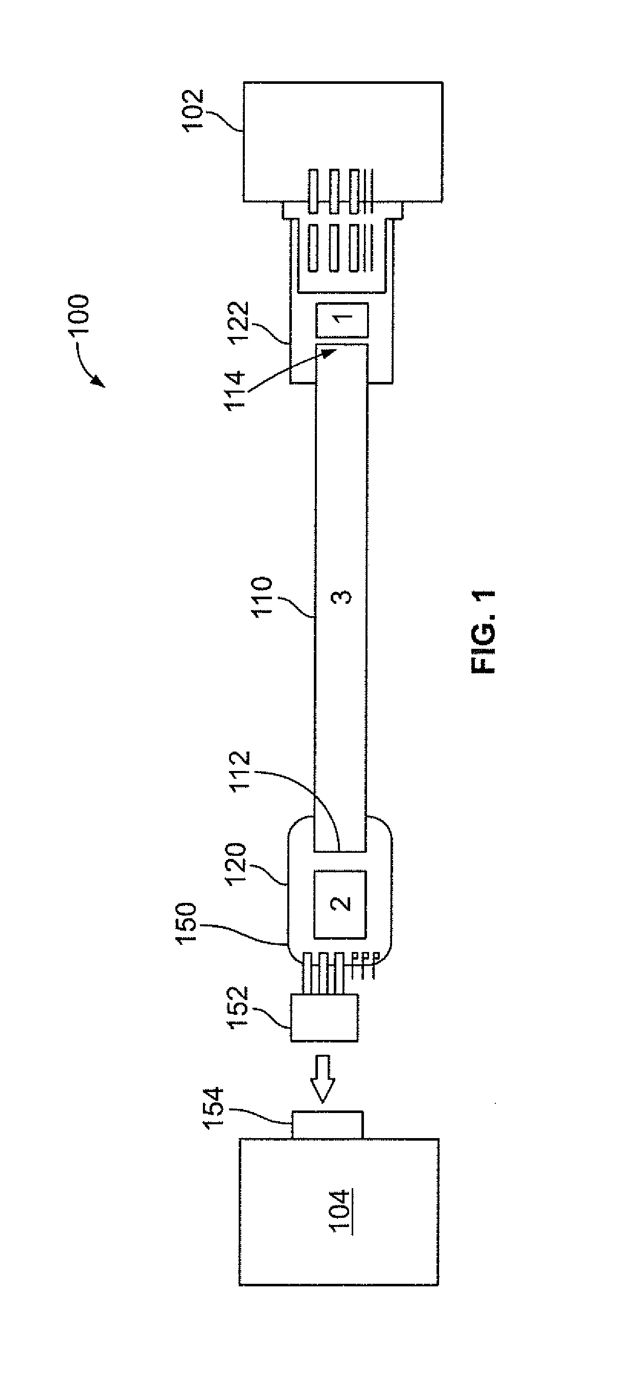
[0014]FIG. 1 illustrates electric vehicle supply equipment (EVSE) system 100 formed in accordance with an exemplary embodiment. The EVSE system 100 is configured to enable an electric vehicle 102 to be coupled to, or uncoupled from, a power supply 104. In operation, the EVSE system 100 enables the electric vehicle 102 to be charged via power received from the power supply 104 when in the coupled configuration and to be electrically uncoupled from the power supply 104 in the uncoupled configuration.

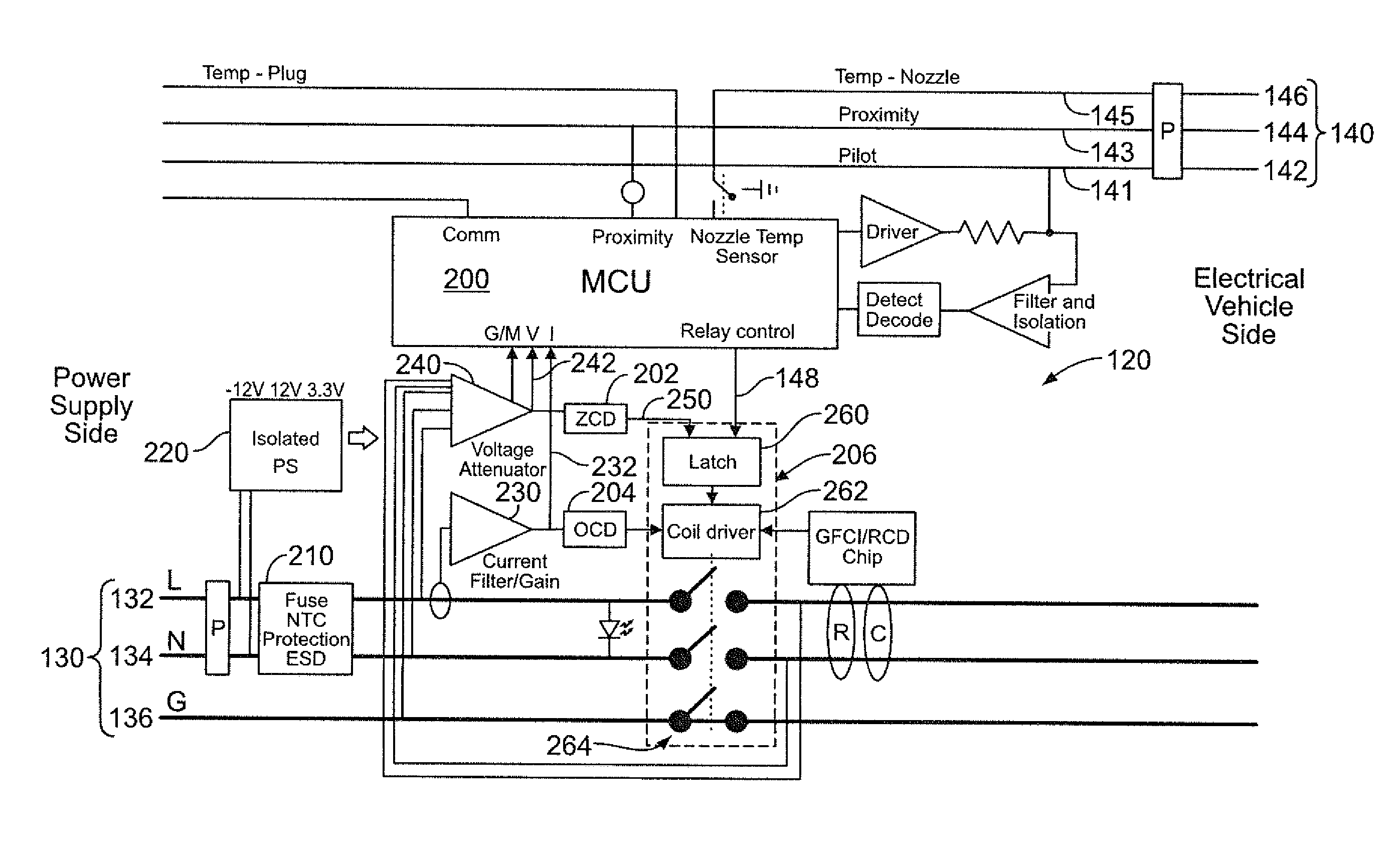
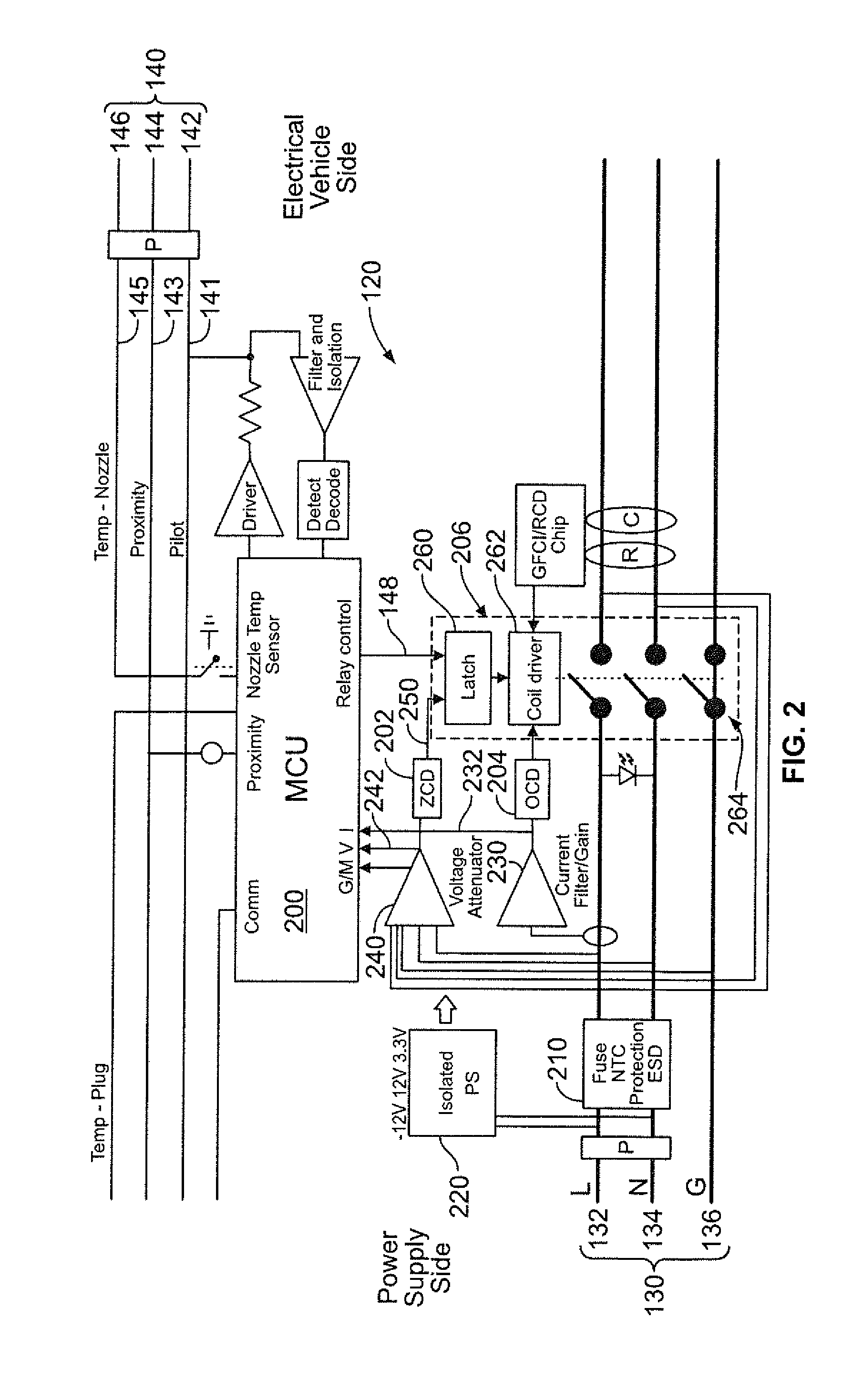
[0015]The EVSE system 100 generally includes a cable 110 having a first end 112 and an opposing second end 114. The EVSE system 100 further includes a smart plug 120 that is coupled to the cable first end 112 and a nozzle 122 that is coupled to the cable second end 114.

[0016]The smart plug 120 may be embodied as a charging circuit interrupt device (CCID) 150 that is configured to connect the electric vehicle 102 to the power supply 104. In operation, the CCID 150 controls the current being...


PUM


Abstract

A smart plug for coupling an electric vehicle to a power supply includes a relay including contacts, the relay configured to operate in a closed state to enable power to be supplied to the electric vehicle and an open state to prohibit power from being supplied to the electric vehicle. The smart plug also includes a microcontroller (MCU) coupled to the relay, the microcontroller outputting a control signal to operate the relay in the closed state. The smart plug further includes a zero crossing detector (ZCD) coupled to the relay, the ZCD outputting a close signal to the relay when a voltage of the power is substantially zero and outputting an open signal to the relay when a current of the power is substantially zero.

Description

BACKGROUND OF THE INVENTION[0001]The subject matter herein relates generally to electric vehicle support equipment having a smart plug with a control circuit for operating a relay.[0002]Relays are used in different types of applications. One application is an automotive application for connecting an electrical vehicle to an external power source. In operation, the relay is activated to enable a charging current to be delivered to the electrical vehicle. The relay is then deactivated to prevent the charging current from being delivered to the electrical vehicle.[0003]In circuits that convey relatively high levels of current, such as the circuits utilized to charge electric vehicles, electric arcs may be generated inside the relay when the contacts within the relay are repositioned from the de-activated state, referred to herein as breaking the contacts, to the activated state, referred to herein as making the contacts. Because the relay is an electromechanical device, the relay exhib...

Claims


Application Information

Patent Timeline
Patent Type & Authority Patents(United States)
IPC IPC(8): H01H47/02H01H47/04B60L3/04B60L3/00B60L11/18H01H47/10H01H47/22H01H83/20H01H9/56
CPCH01H47/02B60L3/0046B60L3/04B60L11/1818B60L11/1846H01H47/04H01H47/10H01H47/22B60L2230/12B60L2240/36B60L2240/527B60L2240/529B60L2270/20H01H9/56H01H83/20Y02T10/7005Y02T10/7088Y02T90/121Y02T90/128Y02T90/14Y02T90/163Y02T90/169Y04S30/14B60L53/16B60L53/65B60L53/18Y02T10/7072Y02T10/70Y02T90/12Y02T90/167Y02T90/16
Inventor HASSAN-ALI, MUDHAFARLARSON, JASON
Owner TYCO ELECTRONICS LOGISTICS AG (CH)
Why Eureka
Try Eureka