
Support assembly and components

a technology of supporting assembly and components, applied in the field of oil and natural gas, can solve the problems of uneconomical use practice of skid or pallet components, increased cost of storage and transportation, and high cost of components formed of wood

Active Publication Date: 2016-09-13
CO BLACK LLC
View PDF76 Cites 6 Cited by
  • Summary
  • Abstract
  • Description
  • Claims
  • Application Information

AI Technical Summary

Benefits of technology

The present invention provides a support assembly for heavy objects such as pipeline segments. The assembly includes a base tier and at least one upper tier. Each tier includes a set of plies of corrugated cardboard secured together with a biodegradable adhesive, and coated with a biodegradable material. The beams of each tier are angled, and in some embodiments, additional beams may be added. The beams have recesses on their surfaces for locking engagement with the beams of a successive tier. A beam in the highest tier has a depression for accommodating a pipeline segment. The invention is advantageous because it allows for a more stable and secure support of heavy objects, while also being environmentally friendly.

Problems solved by technology

Such practice of use of such skid or pallet components has been found to be uneconomical.
Initially, it is to be noted that such components being formed of wood are expensive.
Such cost further is increased by the costs of storing, transporting to and from an assembly storage and use sites, handling at use sites and discarding damaged or worn components.

Method used


Image

  • Support assembly and components
  • Support assembly and components
  • Support assembly and components

Examples


Embodiment Construction

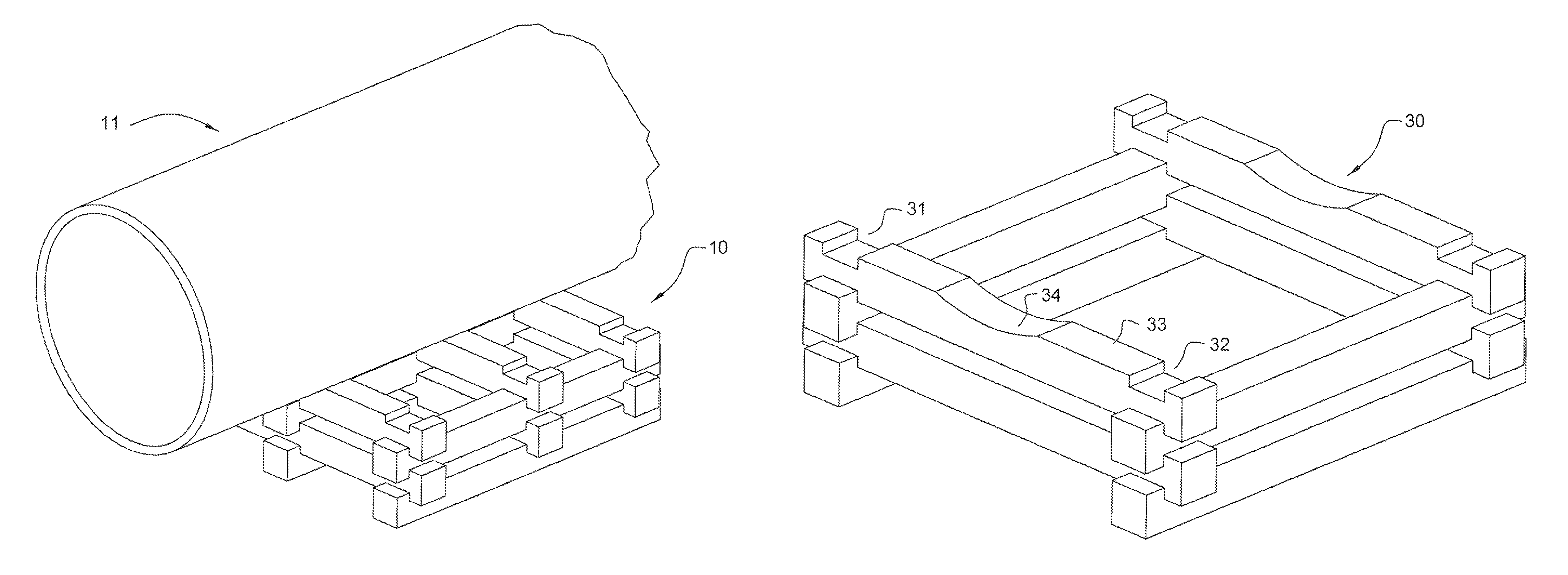
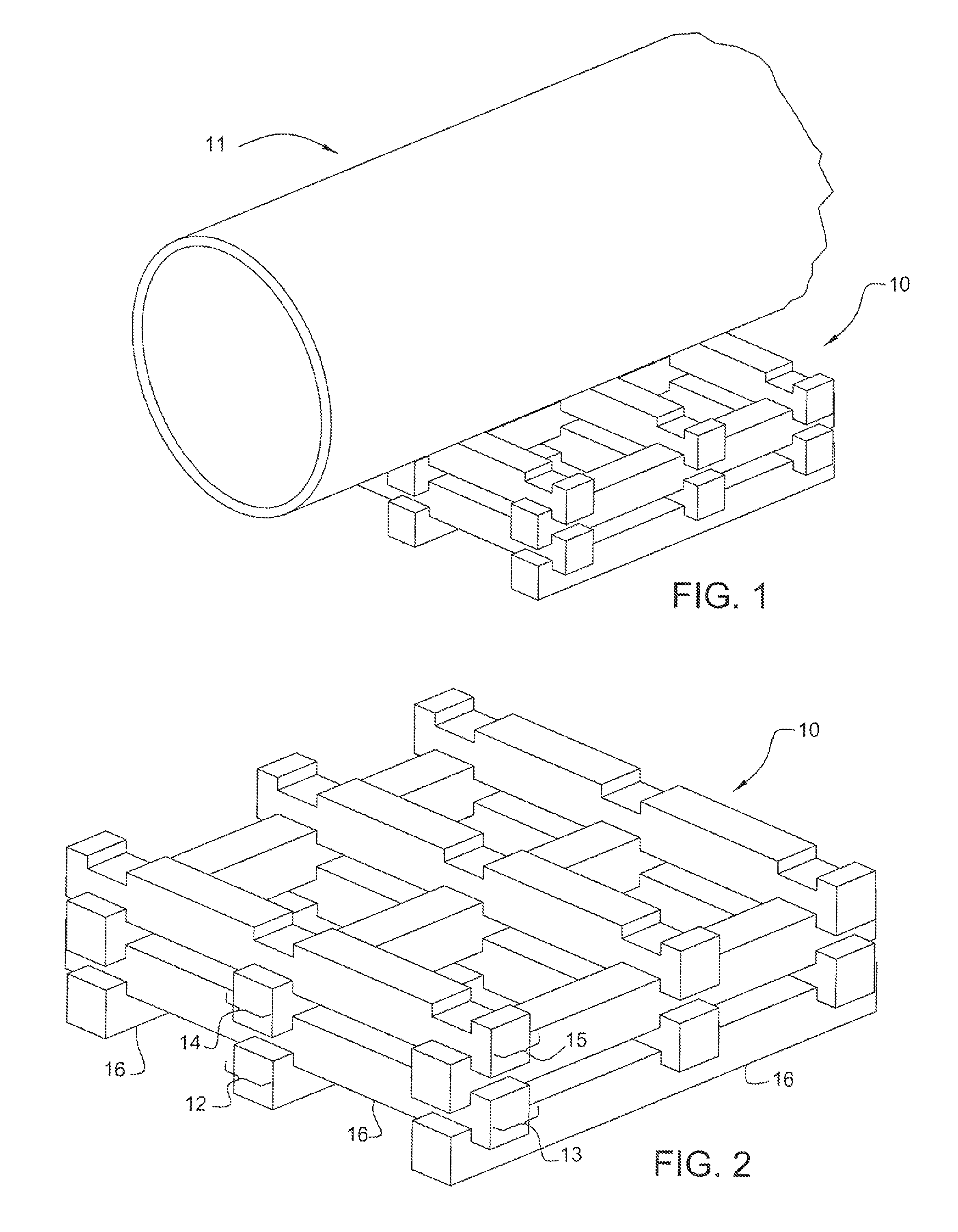
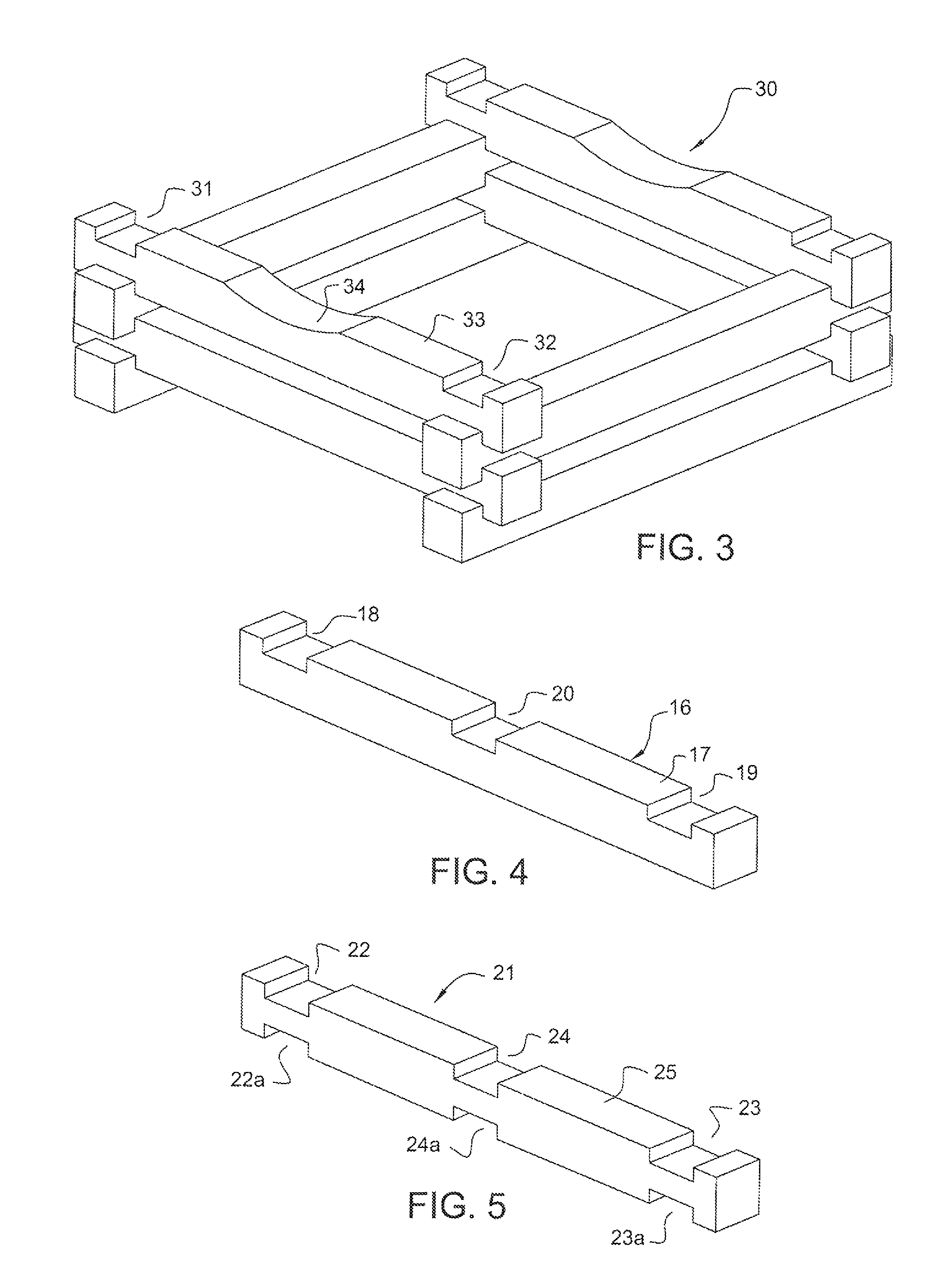
[0018]Referring to FIGS. 1 and 2 of the drawings, there is shown a first embodiment of the invention including an assembly 10 supporting a portion of a pipeline segment 11, providing a base tier 12 and a set of upper tiers 13, 14 and 15, each provided with a set of beams 16 as shown in FIG. 4. As best shown in FIG. 4, each beam 16 is generally rectangulary configured with an elongated rectangular surface 17 provided with a pair of spaced recesses 18 and 19 disposed adjacent the ends thereof and a centrally disposed recess 20 between recesses 18 and 19. Base tier 12 of assembly 10 includes a set of three parallel, spaced beams 16, with the recesses 18, 19 and 20 of each of such beams aligned with comparable recesses in each of the other two beams of such tier. Each of the upper tiers 13, 14 and 15 includes a set of three parallel, spaced beams 16, with the recesses 18, 19 and 20 of each of such beams aligned with comparable recesses in each of the other two beams of such tier, with e...


PUM


Abstract

A member formed of a set of elongated corrugated cardboard plies secured together with a biodegradable adhesive along the lengths thereof and coated with a biodegradable coating which may be stacked to form a support for a portion of an elongated weighty member.

Description

[0001]This invention relates to an assembly of components for supporting a weighty object such as a large metal pipe, and more particularly to such an assembly in which the components thereof are simple in design, formed of comparatively inexpensive materials, lightweight, easily fabricated, easily transportable and manually handled, capable of sustaining heavy loads and readily disposable after effective usage.BACKGROUND OF THE INVENTION[0002]in the oil and natural gas industries, it is a common practice to transmit fluid commodities from one site to another. Such practice generally consists of forming a trench between such sites, providing and placing a transmission pipeline in such trench and filling such trench with excavated soil to permanently bury such pipeline. Typically, following the formation of such trench, segments of such pipeline are transported to successive locations along and adjacent a trench line, mounted on skids or pallets in end-to end relation, welded togethe...

Claims


Application Information

Patent Timeline
Patent Type & Authority Patents(United States)
IPC IPC(8): B65D19/00B65D19/20
CPCB65D19/20B65D2519/00562B65D2519/00567B65D2519/00825B65D19/0085B65D19/44B65D2519/00019B65D2519/00054B65D2519/00273B65D2519/00293B65D2519/00333B65D2519/00796B65D2519/00815F16L1/0246F16L1/06F16L3/02Y02W90/10
Inventor PRATT, WILLIAM K.
Owner CO BLACK LLC
Learn More