Supercharge Your Innovation With Domain-Expert AI Agents!

View angle-restriction sheet and flat panel display

a technology of angle restriction which is applied in the field of view angle restriction sheet and flat panel display, can solve the problems of privacy, information may be used for improper purposes, and leakage of personal information, and achieve the effect of reducing the luminance of the front fa

Active Publication Date: 2016-09-20
KEIWA INCORPORATED
View PDF16 Cites 3 Cited by
  • Summary
  • Abstract
  • Description
  • Claims
  • Application Information

AI Technical Summary

Benefits of technology

[0008]The present invention was made in view of the foregoing circumstances, and an object of the present invention is to provide: a view angle-restricting sheet capable of suitably preventing leakage of personal information and the like through glimmering from an oblique direction and capable of inhibiting a reduction in front face luminance; and a flat panel display that includes the view angle-restricting sheet.

Problems solved by technology

However, in some places, an image displayed on the mobile phones or the personal digital assistances is highly likely to be subjected to peeking by person(s) around a user, which causes an issue of privacy such as leakage of personal information.
Such flat panel displays that include the touchscreen are employed in ATMs (automated teller machines) installed in banks, for example; however, if a security code or personal information is subjected to peeking by person(s) around a user when the user inputs the security code or personal information through the touchscreen, such information may be used for improper purposes.
However, in the view angle-controlling optical sheet, the light-absorbing sections are arranged at a constant interval, and therefore the view angle-controlling optical sheet has a disadvantage that a reduction in front face luminance is likely to be caused.

Method used


Image

  • View angle-restriction sheet and flat panel display
  • View angle-restriction sheet and flat panel display
  • View angle-restriction sheet and flat panel display

Examples


first embodiment

View Angle-Restricting Sheet 1

[0036]Hereinafter, preferred modes for carrying out the present invention will be explained in more detail with reference to the drawings, if necessary.

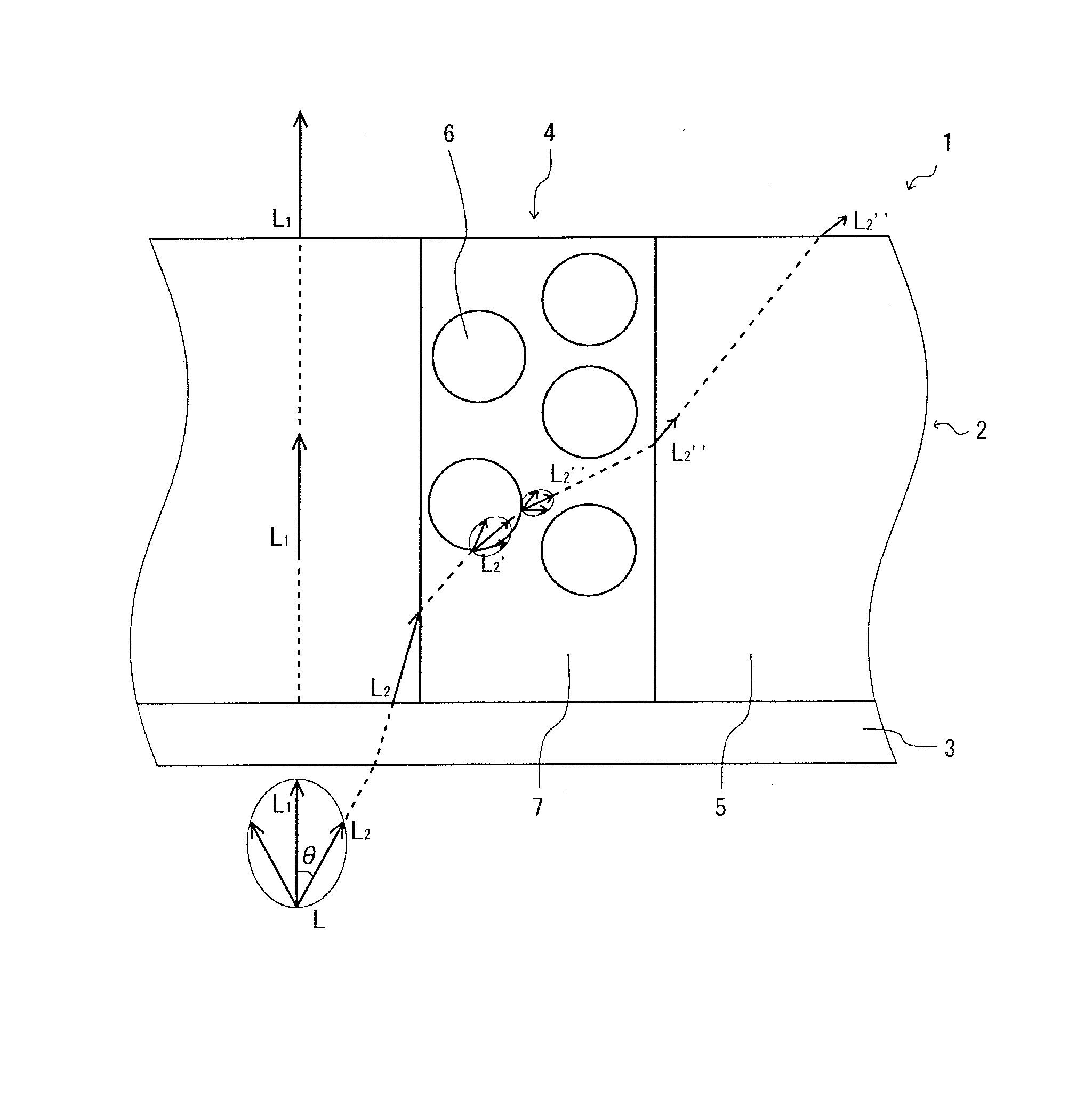
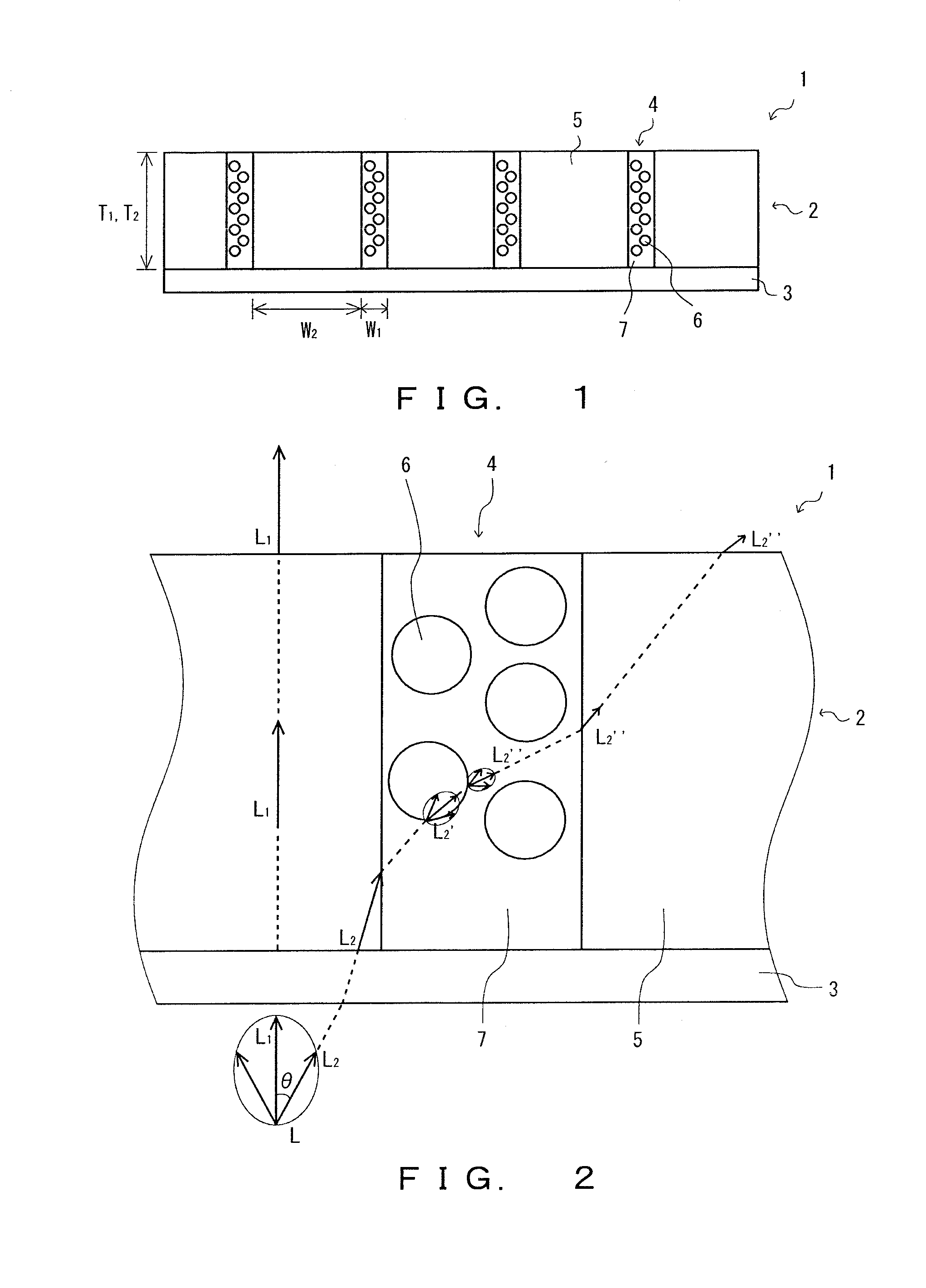
[0037]A view angle-restricting sheet 1 shown in FIG. 1 includes an optically functional layer 2 and a protective layer 3.

[0038]Optically Functional Layer 2

[0039]The optically functional layer 2 includes: a plurality of first light transmission sections 4 that are rectangular in cross section and arranged in a multi-stripe fashion; and a plurality of second light transmission sections 5 that are rectangular in cross section and arranged in a multi-stripe fashion. In the optically functional layer 2, the first light transmission sections 4 are arranged substantially parallel to each other at intervals, and each of the second light transmission sections 5 is arranged between adjacent first light transmission sections 4. The front face and the back face of the optically functional layer 2 are formed to be en...

second embodiment

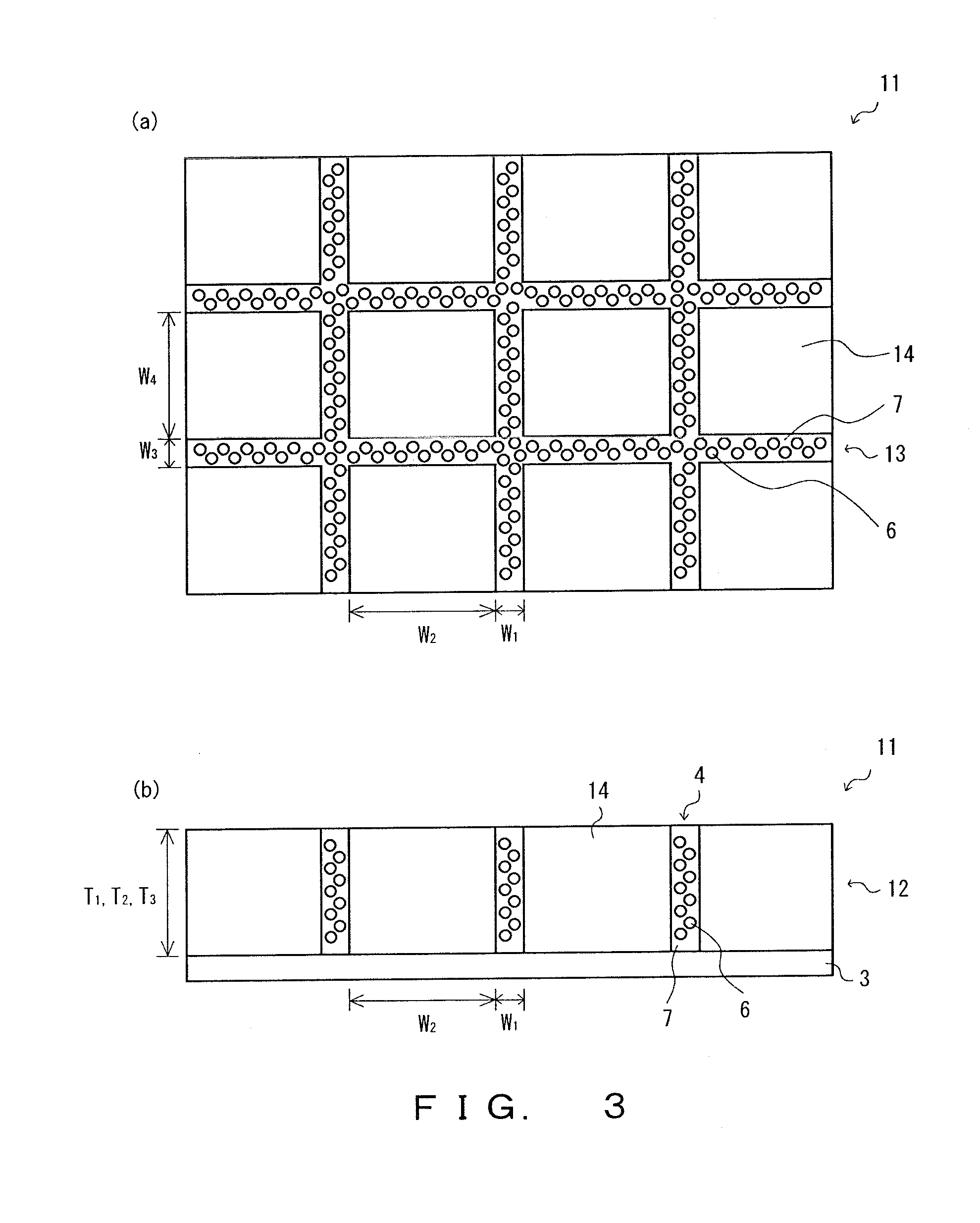
View Angle-Restricting Sheet 11

[0100]The view angle-restricting sheet 11 shown in FIG. 3 includes an optically functional layer 12 and a protective layer 3. Since the protective layer 3 in this embodiment is similar to the protective layer 3 shown in FIG. 1, explanation thereof will be omitted through designating the identical number.

[0101]Optically Functional Layer 12

[0102]The optically functional layer 12 includes: a plurality of first light transmission sections 4 that are rectangular in cross section and arranged in a multi-stripe fashion; second light transmission sections 14 each arranged between adjacent first light transmission sections 4; and third light transmission sections 13 provided crosswise with respect to the first light transmission section 4. Since the first light transmission section 4 in this embodiment is similar to the first light transmission section 4 shown in FIG. 1, explanation thereof will be omitted through designating the identical number. The third lig...

third embodiment

Touchscreen 21

[0109]A touchscreen 21 shown in FIG. 4 includes a substrate 22, a transparent electrically conductive layer 23, a tacky layer 24, a substrate 25, and a view angle-restricting sheet 1. In this embodiment, the view angle-restricting sheet 1 is similar to the view angle-restricting sheet 1 shown in FIG. 1, and therefore explanation thereof will be omitted through designating the identical number. The touchscreen 21 is provided on the front face side of a display panel (not shown in the Figure). The touchscreen 21 allows an image light emitted from the display panel to exit toward the front face side. The touchscreen 21 is provided as a capacitive touchscreen.

[0110]The substrate 22 is made from a transparent insulating material. Specifically, the substrate 22 is provided as a glass substrate. The transparent electrically conductive layer 23 is made from an electrically conductive material having transparency and electric conductivity. A material for forming the transparent...


PUM

PropertyMeasurementUnit
refractive indexaaaaaaaaaa
distanceaaaaaaaaaa

Abstract

The view angle-restricting sheet includes an optically functional layer including: a plurality of first light transmission sections that are rectangular in cross section and arranged in a multi-stripe fashion; and one or more second light transmission section(s) that is / are each arranged between adjacent first light transmission sections. The first light transmission sections contain a light diffusing agent and a resin matrix. The proportion of the surface area occupied by the first light transmission sections with respect to the surface area of the optically functional layer is no less than 5% and no greater than 40%. The ratio (T1 / W1) of the thickness (T1) to the width (W1) of the first light transmission section is preferably no less than 4 and no greater than 40. The average distance between adjacent first light transmission sections is preferably no less than 6 μm and no greater than 400 μm.

Description

TECHNICAL FIELD[0001]The present invention relates to a view angle-restricting sheet and a flat panel display.BACKGROUND OF THE INVENTION[0002]Flat panel displays are intensively used as information display devices such as mobile phones, personal digital assistances (PDAs), personal computers and televisions.[0003]As far as the mobile phones and the personal digital assistances are concerned, for example, the flat panel displays provide advantages that: they enable necessary information to be obtained wherever the information is desired; and the like. However, in some places, an image displayed on the mobile phones or the personal digital assistances is highly likely to be subjected to peeking by person(s) around a user, which causes an issue of privacy such as leakage of personal information.[0004]In addition, some flat panel displays include a touchscreen in order to improve ease of operation for users, speedy operability, and the like. Such flat panel displays that include the to...

Claims


Application Information

Patent Timeline
Patent Type & Authority Patents(United States)
IPC IPC(8): G02B5/02G09F19/12G02F1/1335G09F19/14
CPCG02B5/0242G02B5/02G02B5/0205G02B5/0236G02B5/0263G02F1/1335G02F1/133504G02F1/133524G09F19/12G09F19/14
Inventor TSUJI, TAKAHIRO
Owner KEIWA INCORPORATED
Features
  • R&D
  • Intellectual Property
  • Life Sciences
  • Materials
  • Tech Scout
  • Unparalleled Data Quality
  • Higher Quality Content
  • 60% Fewer Hallucinations
Learn More