Imaging device capable of combining images

a technology of composite images and images, applied in the field of composite images, can solve the problems of difficulty in perfectly matching the timing at which the shutter is released, and the timing, luminance and the like of a generated panoramic image are off-balance, so as to reduce the unnaturalness of the composite image

Active Publication Date: 2016-10-11
CASIO COMPUTER CO LTD
View PDF5 Cites 1 Cited by
  • Summary
  • Abstract
  • Description
  • Claims
  • Application Information

AI Technical Summary

Benefits of technology

[0007]An object of the present invention is to provide an imaging device, an image composition device, an image composition method, and a recording medium which are capable of reducing unnaturalness in a composite image.

Problems solved by technology

However, in this technology, it is generally difficult to perfectly match the timing at which the shutter is released and the timing of exposure of the image sensor, when images are being captured.
Accordingly, there is a problem in that the luminance and the like of a generated panoramic image is off-balance.

Method used


Image

  • Imaging device capable of combining images
  • Imaging device capable of combining images
  • Imaging device capable of combining images

Examples


first embodiment

A. First Embodiment

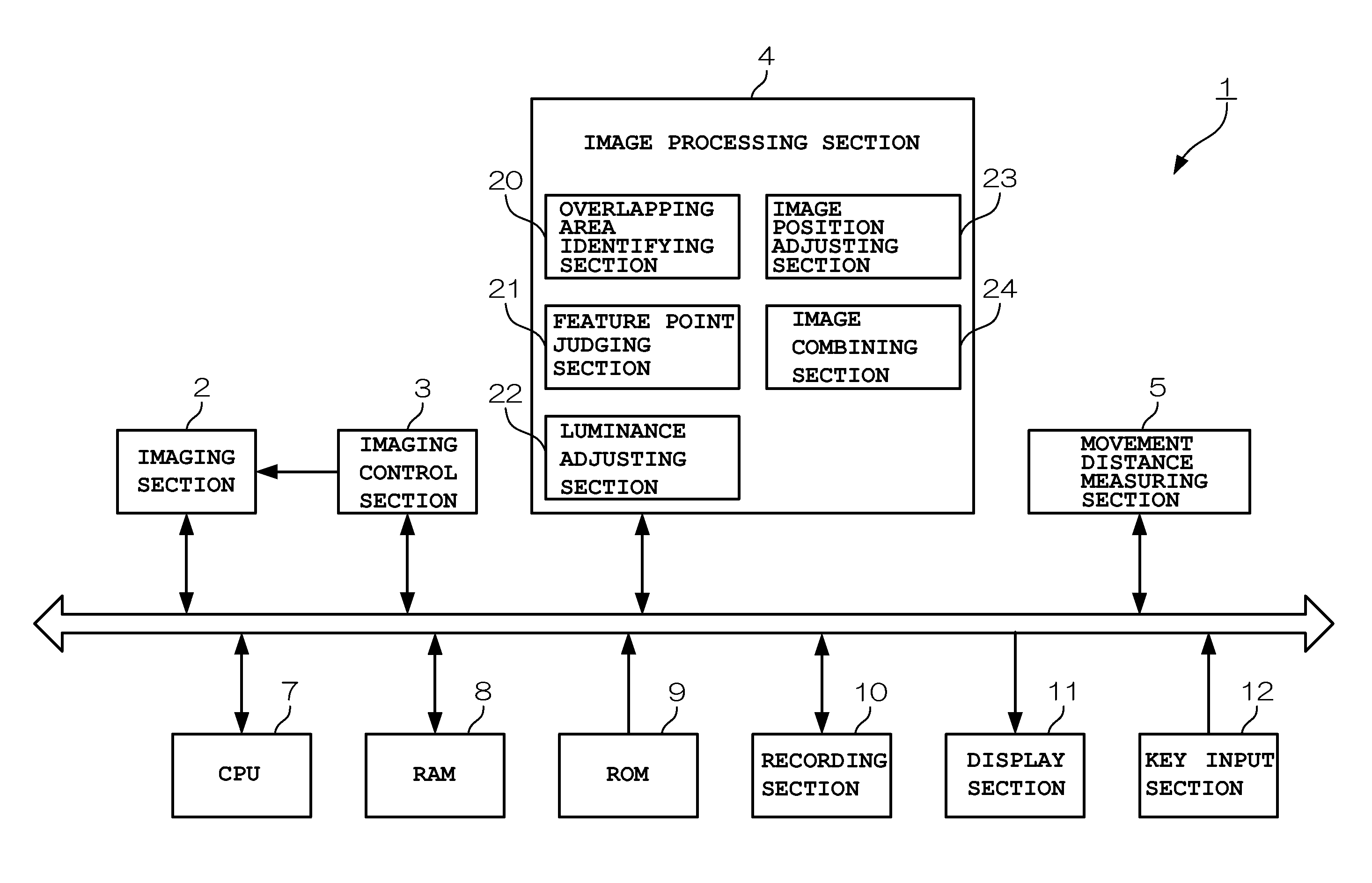
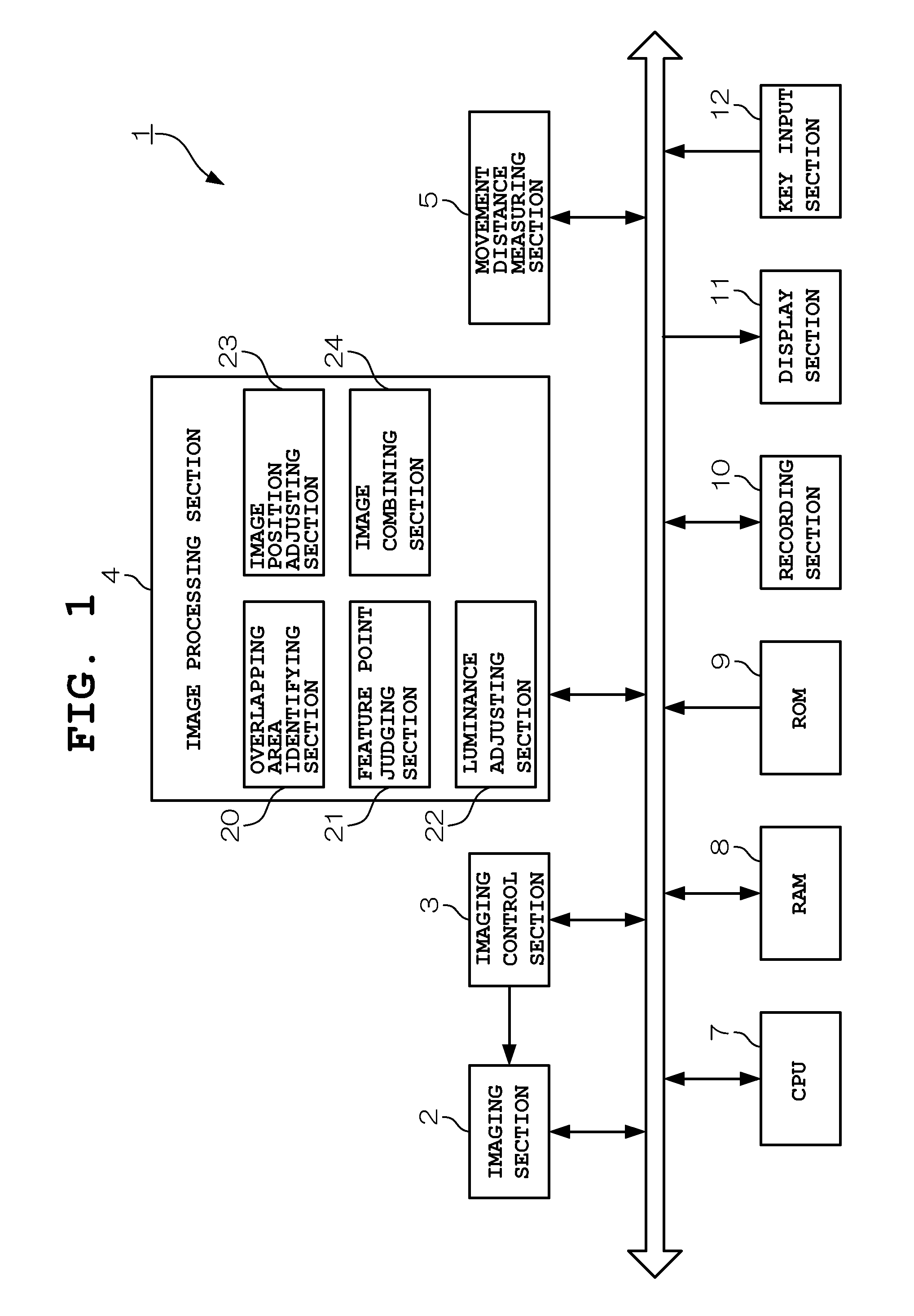
[0022]FIG. 1 is a block diagram showing the configuration of a digital camera 1 according to a first embodiment of the present invention. In FIG. 1, the digital camera 1 includes an imaging section 2 (imaging section, image acquiring section), an imaging control section 3, an image processing section 4, a movement distance measuring section 5, a central processing unit (CPU) 7, a random access memory (RAM) 8, a read-only memory (ROM) 9, a recording section 10, a display section 11 and a key input section 12.

[0023]The imaging section 2 includes a lens group, such as a focus lens and a zoom lens, and an image sensor (such as a charge-coupled device [CCD]), and adjusts auto-focusing, aperture, zooming, and the like in accordance with control signals from the imaging control section 3. This imaging section 2 converts the light of a photographic subject projected via the lens group into electrical signals by using the image sensor, and outputs them as imaging signals. ...

second embodiment

B. Second Embodiment

[0052]Next, a second embodiment of the present invention will be described.

[0053]The second embodiment is characterized in that luminance differences of overlapping areas can be further mitigated when performing image composition by varying the widths (blending widths) of overlapping areas in areas where the amount of texture is larger than a predetermined reference value and in areas where the amount of texture is smaller than the predetermined reference value.

[0054]FIG. 8 to FIG. 10 are conceptual diagrams for explaining operations of the second embodiment. As shown in FIG. 8, the image combining section 24 combines the image for composition 40-1 and the image for composition 40-2 such that the overlapping area 41-1 and the overlapping area 41-2 overlap with each other as in the case of FIG. 6. In each of the upper portions of the overlapping areas 41-1 and 41-2, an area without texture (sky portion) is present.

[0055]Whether the amount of texture is large (area...


PUM


Abstract

A digital camera includes an imaging section, an overlapping area identifying section, a feature point judging section, a luminance adjusting section, and an image combining section. The overlapping area identifying section identifies overlapping areas of images consecutively captured by the imaging section. The feature point judging section judges whether amount of texture within areas of a predetermined range in the identified overlapping areas is larger or smaller than a predetermined reference value. The luminance adjusting section adjusts the pixel values of the images so that the pixel values of the overlapping areas come within a predetermined range, based on a judgment result of the texture. The image combining section combines the adjusted images such that their overlapping areas coincide with each other.

Description

CROSS-REFERENCE TO RELATED APPLICATION[0001]This application is based upon and claims the benefit of priority from the prior Japanese Patent Application No. 2011-077723, filed Mar. 31, 2011, the entire contents of which is incorporated herein by reference.BACKGROUND OF THE INVENTION[0002]1. Field of the Invention[0003]The present invention relates to an imaging device, an image composition device, an image composition method and a recording medium.[0004]2. Description of the Related Art[0005]A conventional technology (for example, refer to Japanese Patent Application Laid-Open (Kokai) Publication No. 06-303562) is known in which, when a user captures images by moving a digital camera substantially held in a vertical direction to rotate in a horizontal direction while pressing the shutter switch, the digital camera generates a panoramic image by combining the captured images such that portions thereof are joined together.[0006]However, in this technology, it is generally difficult to...

Claims


Application Information

Patent Timeline
Patent Type & Authority Patents(United States)
IPC IPC(8): H04N5/232G06T3/40
CPCH04N5/23293G06T3/4038H04N5/23238H04N23/698
Inventor MIYAMOTO, NAOTOMOMATSUMOTO, KOSUKE
Owner CASIO COMPUTER CO LTD
Why Eureka
Try Eureka