Road design optimization

a road design and optimization technology, applied in computer aided design, computation using non-denominational number representation, instruments, etc., can solve the problems of not always being able to follow the ground surface exactly, affecting the cost of earthwork, and being unable to achieve precise follow-up of the ground surface, etc., to achieve large surface profiles, reduce the number of ground points for the centerline, and increase the accuracy

Active Publication Date: 2016-10-25
AUTODESK INC
View PDF2 Cites 3 Cited by
  • Summary
  • Abstract
  • Description
  • Claims
  • Application Information

AI Technical Summary

Benefits of technology

[0022]In embodiments of the invention, only the initial surface profile of the existing ground at the road centerline is needed as input. To increase the accuracy, a user may also provide ground surface profile offsets. In order to handle very large surface profiles, the invention may use the Douglas-Peucker method to reduce the number of ground points for the centerline. For the resulting ground points, the invention may then use a segmented least-squares methodology to create an initial set of PVI's. The invention optimizes the exact location of each PVI with respect to elevation and horizontal position along the profile. For that, the invention uses a continuous bi-level method. The invention may use a Stochastic Optimization methodology in the bi-level method. The user can provide a single surface profile only, or additional offset profiles, which render the solution more accurately. Furthermore, the bi-level method may use an LP model in a novel manner to handle multiple surfaces with different earthwork costs, and mixed materials for filling gaps.

Problems solved by technology

From this, one may note that earthwork cost is a major cost component in the construction of roads.
The horizontal alignment determines the overall length of the road, and therefore directly affects the pavement cost.
However, due to design constraints like grade changes, vertical curve length, etc., it is not always possible to follow the ground surface exactly.
However, due to timely and budgetary constraints, a final alignment is often chosen from a small selection of possible solutions.
Furthermore, none of the methods optimizes the exact location of the PVI's with respect to elevation and horizontal position.
Also, the prior art fails to optimize the length of the vertical curves at each PVI.
They do not support the use of additional ground profile offsets.

Method used


Image

  • Road design optimization
  • Road design optimization
  • Road design optimization

Examples


Embodiment Construction

[0034]In the following description, reference is made to the accompanying drawings which form a part hereof, and which is shown, by way of illustration, several embodiments of the present invention. It is understood that other embodiments may be utilized and structural changes may be made without departing from the scope of the present invention.

Overview

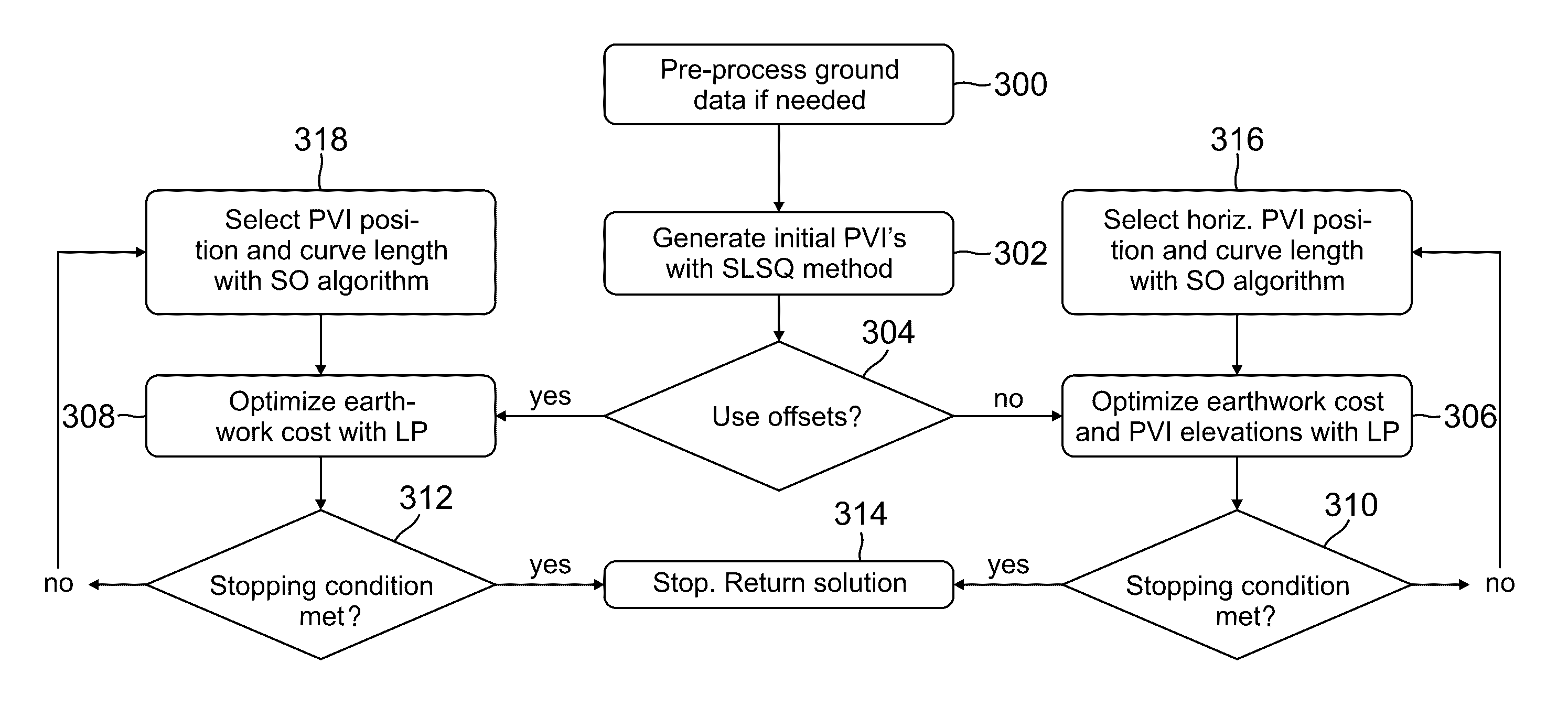
[0035]Embodiments of the invention present a new bi-level system / methodology, that, besides the ground surface profile at the centerline, needs no additional user input. An initial set of PVI's with vertical curves are generated and the position of each PVI is iteratively optimized with respect to elevation and horizontal position, as well as the vertical curve length. The user can provide additional ground surface profiles, that are at an offset from the centerline, in order to increase the accuracy of the solution.

[0036]In addition, embodiments of the invention provide a practical methodology for using multiple soil layers. In this...


PUM


Abstract

A method, apparatus, system, article of manufacture, and computer readable storage medium provide the ability to optimize a design for a vertical road profile. A ground surface profile is obtained. From the ground surface profile, an initial set of points of vertical intersection (PVIs) are obtained. An optimized earthwork cost for the PVIs is determined. The PVIs and curve configurations are then modified to reduce the earth work cost.

Description

CROSS-REFERENCE TO RELATED APPLICATIONS[0001]This application claims the benefit under 35 U.S.C. Section 119(e) of the following and commonly-assigned U.S. provisional patent application(s), which is / are incorporated by reference herein:[0002]Provisional Application Ser. No. 61 / 539,793, filed on Sep. 27, 2011, by Valentin R. Koch, entitled “ROAD DESIGN OPTIMIZATION,”.BACKGROUND OF THE INVENTION[0003]1. Field of the Invention[0004]The present invention relates generally to computer-aided design (CAD) applications, and in particular, to a method, apparatus, and article of manufacture for optimizing road design in a CAD application.[0005]2. Description of the Related Art[0006](Note: This application references a number of different publications as indicated throughout the specification by reference numbers enclosed in brackets, e.g., [x]. A list of these different publications ordered according to these reference numbers can be found below in the section entitled “References.” Each of ...

Claims


Application Information

Patent Timeline
Patent Type & Authority Patents(United States)
IPC IPC(8): G06F7/60G06F17/10G06F17/50
CPCG06F17/5004G06F30/13
Inventor KOCH, VALENTIN R.
Owner AUTODESK INC
Why Eureka
Try Eureka