Drive mechanism for an intermediate transfer member module of an electrophotographic imaging device

a technology of transfer member module and transfer member, which is applied in the field of imaging devices, can solve the problems of negating the benefit of a wide second transfer nip, affecting the drive capability over the life of the transfer belt, and onset of transfer, so as to reduce the amount of torque, reduce the amount of air gap, and reduce the effect of air gap

Active Publication Date: 2016-11-08
LEXMARK INT INC
View PDF5 Cites 2 Cited by
  • Summary
  • Abstract
  • Description
  • Claims
  • Application Information

AI Technical Summary

Benefits of technology

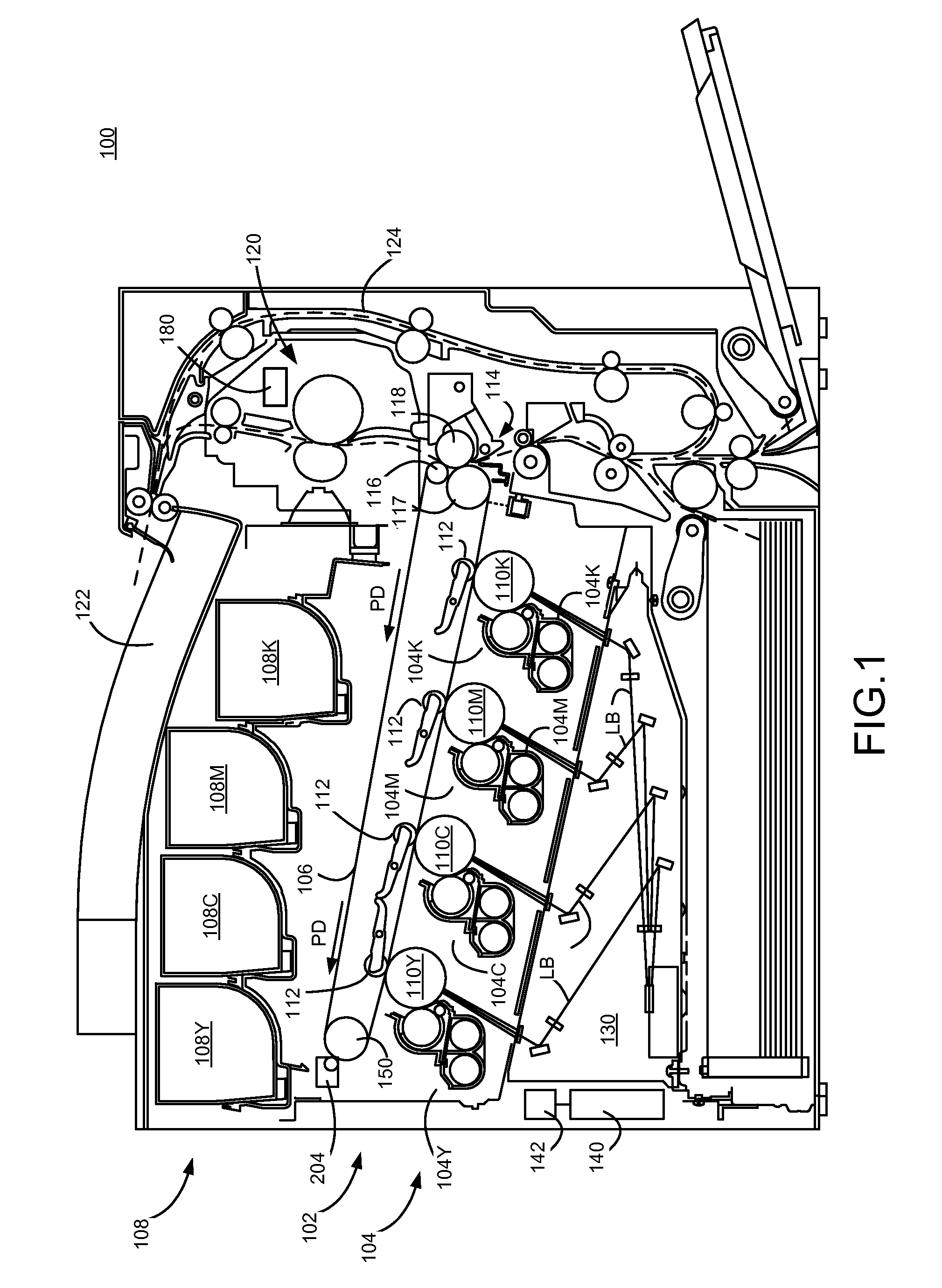
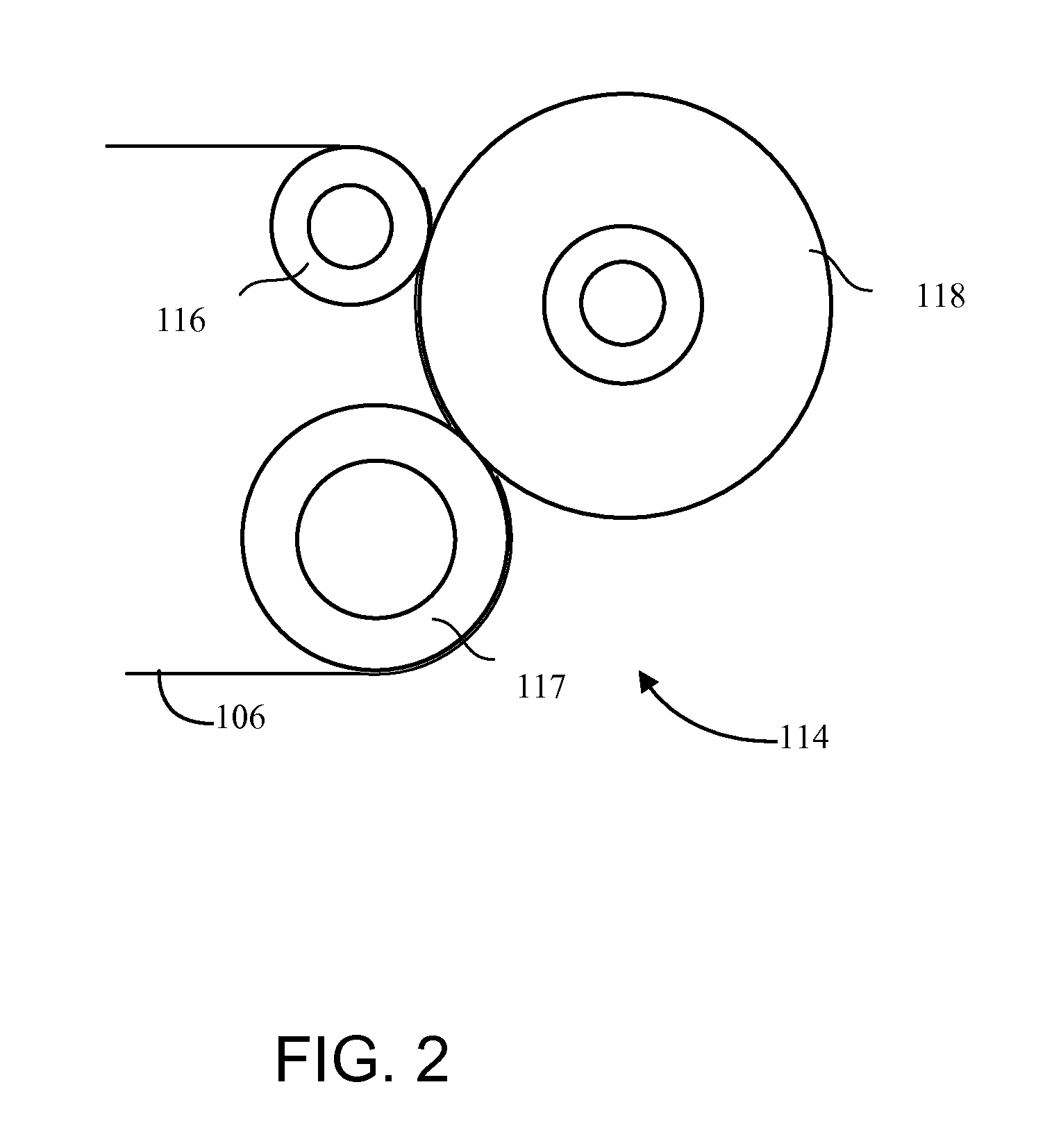
[0012]Example embodiments are directed to an intermediate transfer member (ITM) module for an electrophotographic imaging device, including a frame; a backup roll disposed along a first end portion of the frame, the backup roll being rotatable within the frame and including a backup roll gear; a drive roll disposed along the first end portion of the frame in proximity with the backup roll and including a drive gear; a tension roll disposed along a second end portion of the frame and being rotatable within the frame; and an ITM belt rotatably coupled to the frame. The ITM belt forms as an endless loop around the backup roll, the drive roll and the tension roll such that rotation of the drive roll causes the ITM belt to translate and the tension roll and the backup roll to rotate. The drive roll and the backup roll form at least part of a second transfer nip with a second transfer roll of the electrophotographic imaging device when the ITM module is operably disposed therein. The ITM module further includes a drive mechanism coupled to the drive gear and the backup roll gear and including a plurality of gears and a clutch. In an example embodiment, the drive mechanism tends to overdrive the backup roll relative to the drive roll while limiting an amount of torque applied to the backup roll so as to control an amount of tension of the ITM belt between the drive roll and the backup roll created by overdriving the backup roll. In this way, the example embodiments provide sufficient tension in the ITM belt at the second transfer nip to eliminate or reduce an air gap between the ITM belt and a sheet of media to achieve desired toner transfer characteristics while ensuring that overdriving the backup roll does not create excessive belt tension in the second transfer nip.
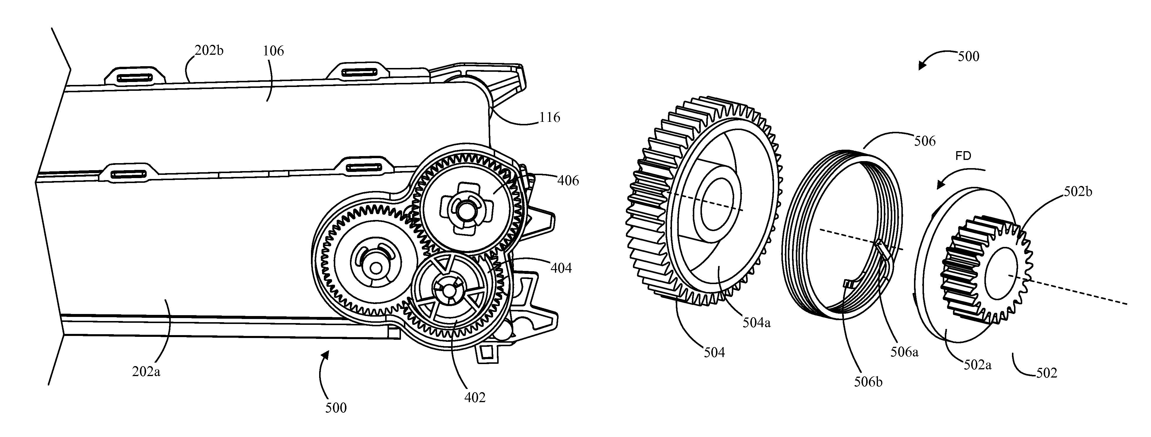
[0013]In an example embodiment, the plurality of gears include a first gear and a second gear and the clutch is coupled between the first gear and the second gear. The first gear is coupled to the drive gear, the second gear is coupled between the first gear and the backup roll gear, and the clutch is a friction clutch. The friction clutch includes a wrap spring with a first end coupled to the first gear and an uncoupled second end. The first gear includes a plate member having a first surface from which gear teeth of the first gear extend and a second surface from which at least one engagement structure extends. The first end of the wrap spring engages with the at least one engagement structure of the first gear such that when the first gear rotates in a first direction, the wrap spring and the second gear rotate with the first gear. The friction clutch limits the amount of torque provided to the second gear by wrap spring slipping relative to the second gear. In this way, excessive tension of the ITM belt in the second transfer nip is avoided despite the backup roll being overdriven relative to the drive roll.

Problems solved by technology

The use of the drive roll as a backup roll at second transfer may result the in transfer belt wrapping less around the drive roll, thereby adversely affecting drive capability over the life of the transfer belt.
Further, the transfer belt may tend to pull away from the media sheet at second transfer, thereby forming an air gap which results in an onset of transfer that occurs later than desired as well as premature Paschen breakdown, thus negating the benefit of a wide second transfer nip.

Method used


Image

  • Drive mechanism for an intermediate transfer member module of an electrophotographic imaging device
  • Drive mechanism for an intermediate transfer member module of an electrophotographic imaging device
  • Drive mechanism for an intermediate transfer member module of an electrophotographic imaging device

Examples


Embodiment Construction

[0022]It is to be understood that the present disclosure is not limited in its application to the details of construction and the arrangement of components set forth in the following description or illustrated in the drawings. The present disclosure is capable of other embodiments and of being practiced or of being carried out in various ways. Also, it is to be understood that the phraseology and terminology used herein is for the purpose of description and should not be regarded as limiting. The use of “including,”“comprising,” or “having” and variations thereof herein is meant to encompass the items listed thereafter and equivalents thereof as well as additional items. Unless limited otherwise, the terms “connected,”“coupled,” and “mounted,” and variations thereof herein are used broadly and encompass direct and indirect connections, couplings, and positionings. In addition, the terms “connected” and “coupled” and variations thereof are not restricted to physical or mechanical con...


PUM


Abstract

An intermediate transfer member (ITM) module including a frame; a backup roll and a drive roll rotatably disposed along a first end portion of the frame. A tension roll is rotatably disposed along a second end portion of the frame. An ITM belt forms as an endless loop around the backup roll, the drive roll and the tension roll such that rotation of the drive roll causes the ITM belt to translate and the tension roll and the backup roll to rotate. The drive roll and the backup roll form a transfer nip with a transfer roll. A drive mechanism is coupled between the drive roll and the backup roll and includes a plurality of gears. The drive mechanism overdrives the backup roll relative to the drive roll while limiting an amount of tension of the ITM belt in the second transfer nip.

Description

CROSS REFERENCES TO RELATED APPLICATIONS[0001]None.STATEMENT REGARDING FEDERALLY SPONSORED RESEARCH OR DEVELOPMENT[0002]None.REFERENCE TO SEQUENTIAL LISTING, ETC.[0003]None.BACKGROUND[0004]1. Field of the Disclosure[0005]The present disclosure relates generally to an imaging device and is particularly directed to an intermediate transfer member (ITM) module of the type which controls the tension of the ITM belt of the ITM module within a predetermined range of tension.[0006]2. Description of the Related Art[0007]Toner transfer is a core process in an electrophotographic printing process. The process starts when a photosensitive roll, such as a photoconductor drum, is charged and then selectively discharged to create a charge image. The charge image is developed by a developer roll covered with charged toner of uniform thickness. This developed image then travels to what is referred to as “first transfer” in the case of a two step transfer system, or the only transfer process in the ...

Claims


Application Information

Patent Timeline
Patent Type & Authority Patents(United States)
IPC IPC(8): G03G15/16
CPCG03G15/1615
Inventor EMBRY, KERRY LELANDGEYLING, ALEXANDER JOHANNESGOULD, II, BARTLEY CHARLESMCALPINE, ROBERT WATSONPORTIG, HARALD
Owner LEXMARK INT INC
Why Eureka
Try Eureka