Treatment device
a treatment device and heat-transfer technology, applied in the field of treatment devices, can solve the problems of increasing the cost of the whole system, increasing the temperature difference between the heat-generating chip and the heat-transfer member, and large flux density from the heat-generating chip to the heat-transfer member, so as to achieve high accuracy of temperature control, small cost, and no malfunction
- Summary
- Abstract
- Description
- Claims
- Application Information
AI Technical Summary
Benefits of technology
Problems solved by technology
Method used
Image
Examples
first embodiment
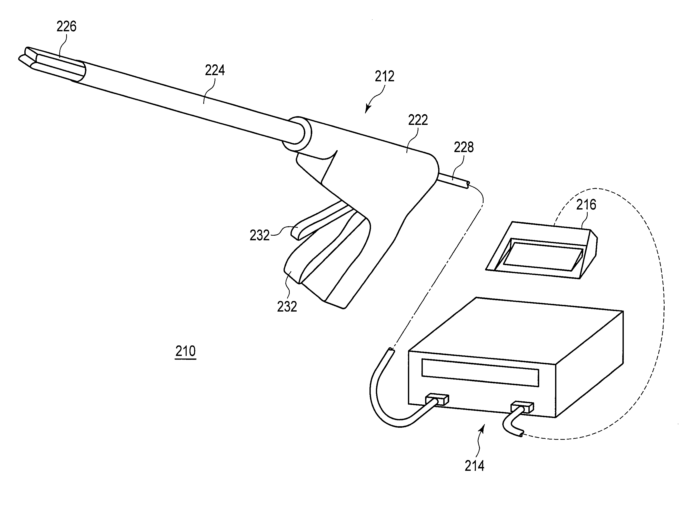
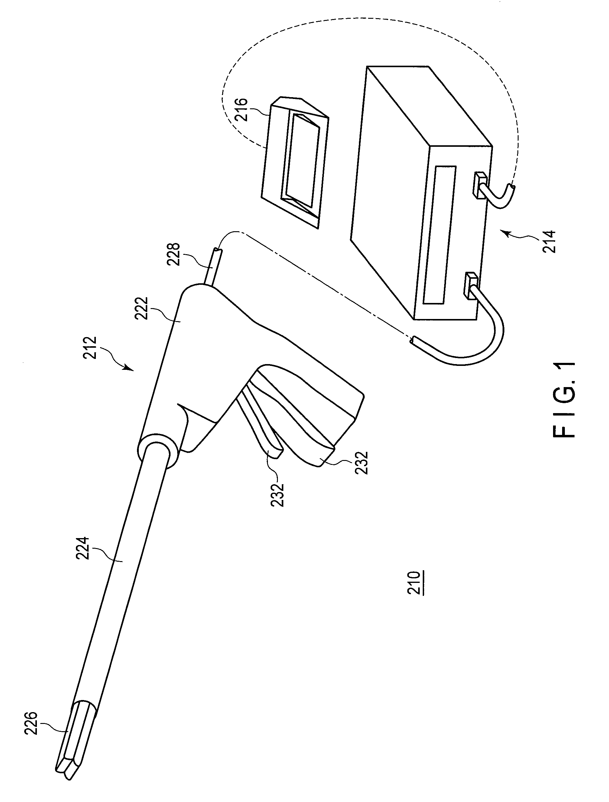
[0030]A first embodiment of the present invention will now be described with reference to the drawings. A treatment device according to the present embodiment is used for treating biotissues, and causes high-frequency energy and thermal energy to act on the biotissues. As illustrated in FIG. 1, the treatment device 210 includes an energy treatment tool 212, an energy source 214, and a foot switch 216.
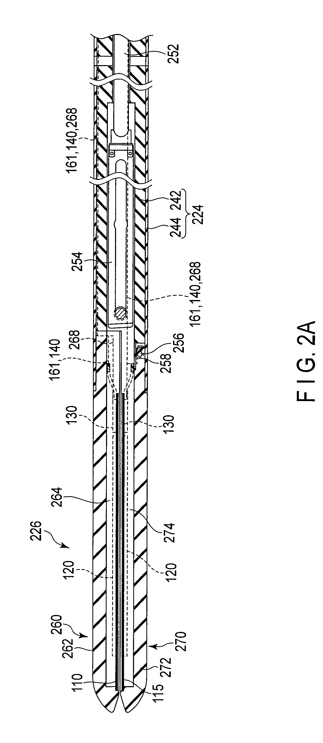
[0031]The energy treatment tool 212 is a linear-type surgical treatment tool to pierce, for example, the abdominal wall and perform treatment. The energy treatment tool 212 includes a handle 222, a shaft 224 attached to the handle 222, and a holder 226 provided at the distal end of the shaft 224. The holder 226 is a treatment unit that is openable and closable, holds the biotissue to be treated, and performs treatment such as coagulation and incision. In the following explanation, the side of the holder 226 is referred to as “distal end side”, and the side of the handle 222 is referred ...
second embodiment
[0097]A second embodiment will be explained hereinafter. In the following explanation, points that are different from the first embodiment will be described, and like constituent elements are denoted by like reference numerals, with explanation thereof omitted. The structure of a treatment device 210 according to the present embodiment is the same as the first embodiment.
[0098]The present embodiment is different from the first embodiment in the condition for switching feedback control using the temperature T1 of the heat-generating member122 to feedback control using the temperature T2 of the thermocouple 140, in temperature control performed by the controller 180. The condition in the present embodiment is that the difference T1-T2 in temperature between the heat-generating member 122 and the thermocouple 140 becomes equal to or less than a threshold Tth1, while the condition in the first embodiment is that the supplied electric power P becomes equal to or less than the threshold P...
third embodiment
[0104]A third embodiment will be explained hereinafter. In the following explanation, points that are different from the first embodiment will be described, and like constituent elements are denoted by like reference numerals, with explanation thereof omitted. The structure of a treatment device 210 according to the present embodiment is the same as the first embodiment.
[0105]The present embodiment is different from the first embodiment in the condition for switching feedback control using the temperature T1 of the heat-generating member 122 to feedback control using the temperature T2 of the thermocouple 140, in temperature control performed by the controller 180. The condition in the present embodiment is that the temperature T2 of the thermocouple 140 becomes equal to or greater than a threshold Tth2, while the condition in the first embodiment is that the supplied electric power P becomes equal to or less than the threshold Pth.
[0106]FIG. 11 illustrates a flowchart of temperatur...
PUM
 Abstract
Description
Claims
Application Information
 - R&D
- Intellectual Property
- Life Sciences
- Materials
- Tech Scout
- Unparalleled Data Quality
- Higher Quality Content
- 60% Fewer Hallucinations
Browse by: Latest US Patents, China's latest patents, Technical Efficacy Thesaurus, Application Domain, Technology Topic, Popular Technical Reports.
© 2025 PatSnap. All rights reserved.Legal|Privacy policy|Modern Slavery Act Transparency Statement|Sitemap|About US| Contact US: help@patsnap.com


