Treatment device

a treatment device and heat-transfer technology, applied in the field of treatment devices, can solve the problems of increasing the cost of the whole system, increasing the temperature difference between the heat-generating chip and the heat-transfer member, and large flux density from the heat-generating chip to the heat-transfer member, so as to achieve high accuracy of temperature control, small cost, and no malfunction

Active Publication Date: 2014-03-13
OLYMPUS CORP
View PDF4 Cites 7 Cited by
  • Summary
  • Abstract
  • Description
  • Claims
  • Application Information

AI Technical Summary

Benefits of technology

[0008]The object of the present invention is to provide a treatment device that enables highly accurate control of the temperature for heating a biotissue at small cost and without malfunction.

Problems solved by technology

As a result, the heat flux density from the heat-generating chip to the heat-transfer member becomes very large, and a difference in temperature between the heat-generating chip and the heat-transfer member increases.
This increases the cost of the whole system.

Method used


Image

  • Treatment device
  • Treatment device
  • Treatment device

Examples


first embodiment

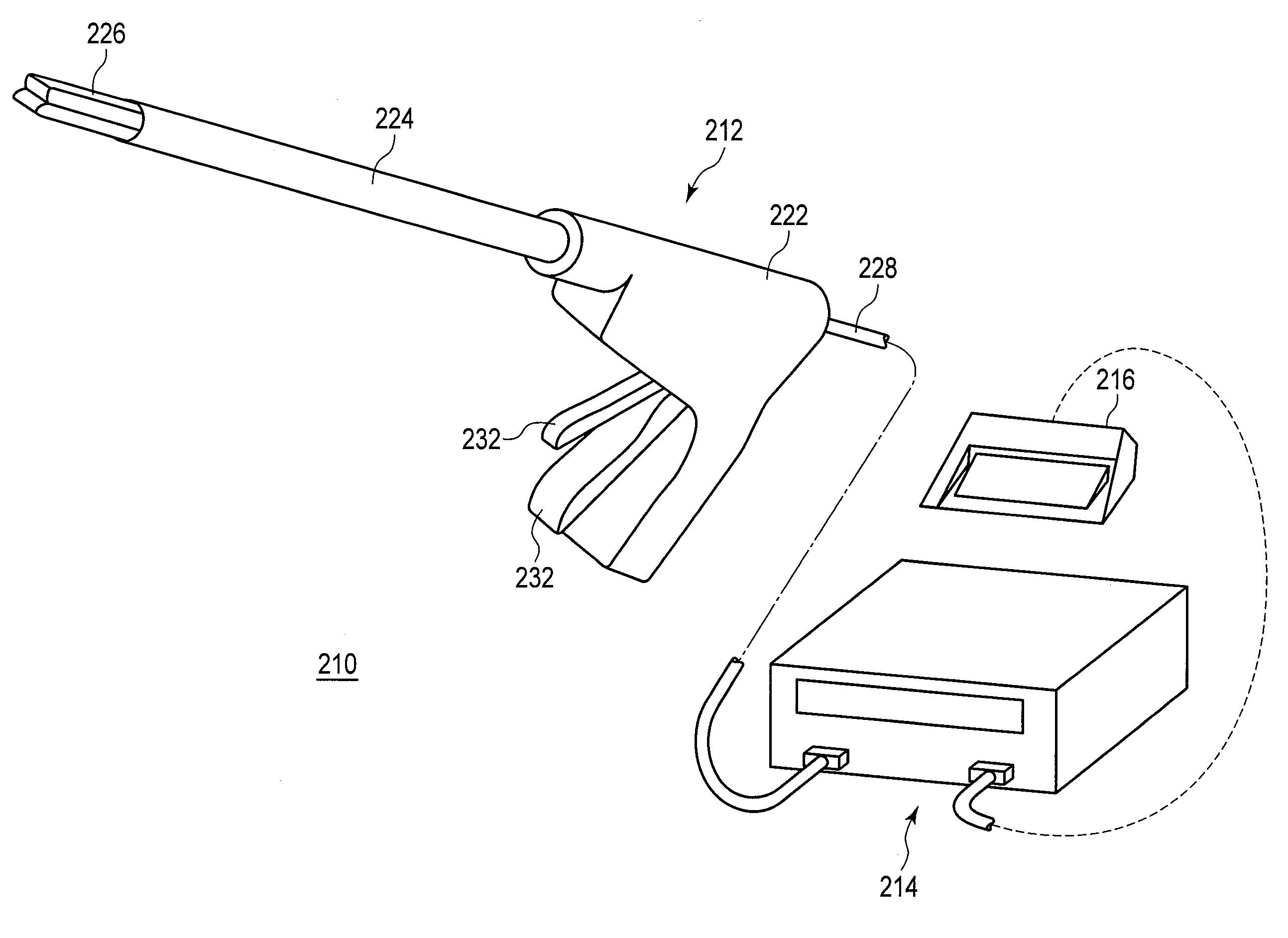
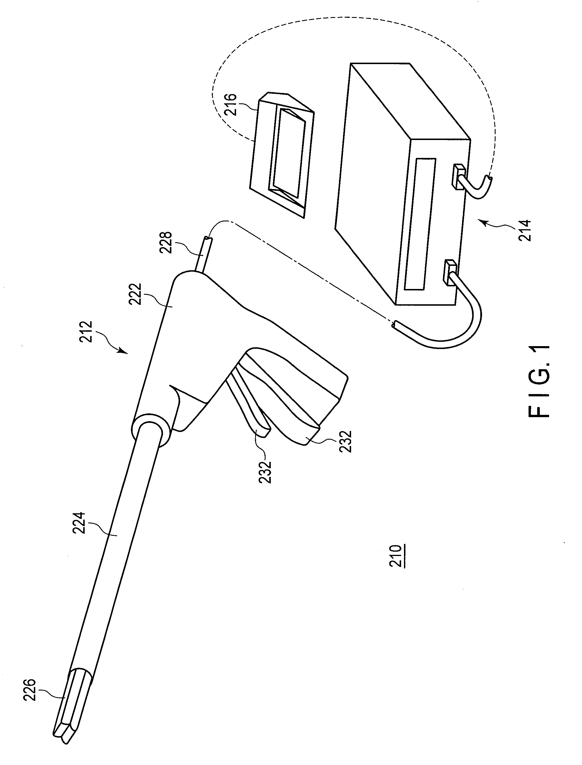
[0030]A first embodiment of the present invention will now be described with reference to the drawings. A treatment device according to the present embodiment is used for treating biotissues, and causes high-frequency energy and thermal energy to act on the biotissues. As illustrated in FIG. 1, the treatment device 210 includes an energy treatment tool 212, an energy source 214, and a foot switch 216.

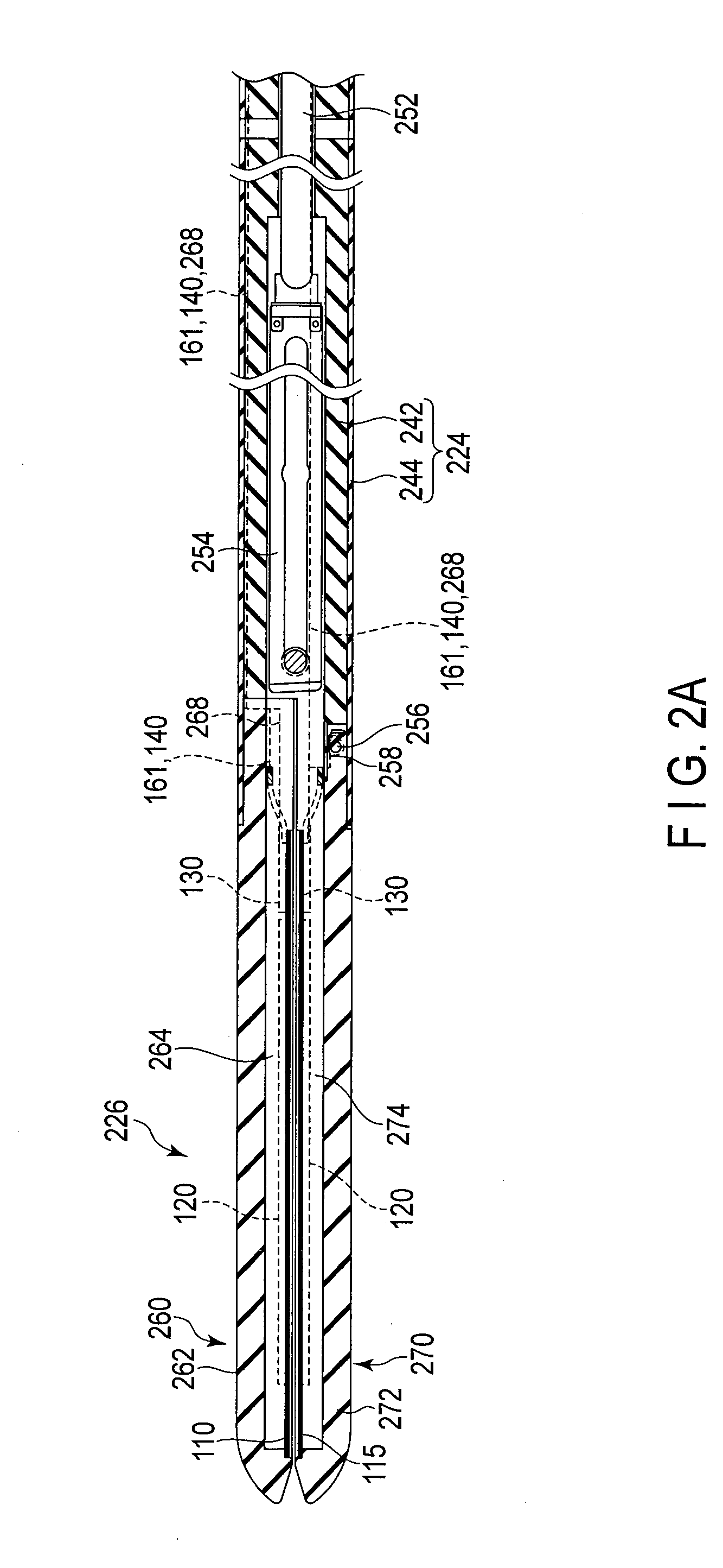
[0031]The energy treatment tool 212 is a linear-type surgical treatment tool to pierce, for example, the abdominal wall and perform treatment. The energy treatment tool 212 includes a handle 222, a shaft 224 attached to the handle 222, and a holder 226 provided at the distal end of the shaft 224. The holder 226 is a treatment unit that is openable and closable, holds the biotissue to be treated, and performs treatment such as coagulation and incision. In the following explanation, the side of the holder 226 is referred to as “distal end side”, and the side of the handle 222 is referred ...

second embodiment

[0095]A second embodiment will be explained hereinafter. In the following explanation, points that are different from the first embodiment will be described, and like constituent elements are denoted by like reference numerals, with explanation thereof omitted. The structure of a treatment device 210 according to the present embodiment is the same as the first embodiment.

[0096]The present embodiment is different from the first embodiment in the condition for switching feedback control using the temperature T1 of the heat-generating member 122 to feedback control using the temperature T2 of the thermocouple 140, in temperature control performed by the controller 180. The condition in the present embodiment is that the difference T1-T2 in temperature between the heat-generating member 122 and the thermocouple 140 becomes equal to or less than a threshold Tth1, while the condition in the first embodiment is that the supplied electric power P becomes equal to or less than the threshold ...

third embodiment

[0102]A third embodiment will be explained hereinafter. In the following explanation, points that are different from the first embodiment will be described, and like constituent elements are denoted by like reference numerals, with explanation thereof omitted. The structure of a treatment device 210 according to the present embodiment is the same as the first embodiment.

[0103]The present embodiment is different from the first embodiment in the condition for switching feedback control using the temperature T1 of the heat-generating member 122 to feedback control using the temperature T2 of the thermocouple 140, in temperature control performed by the controller 180. The condition in the present embodiment is that the temperature T2 of the thermocouple 140 becomes equal to or greater than a threshold Tth2, while the condition in the first embodiment is that the supplied electric power P becomes equal to or less than the threshold Pth.

[0104]FIG. 11 illustrates a flowchart of temperatur...


PUM


Abstract

A treatment device treats a biotissue by heating the biotissue to a target temperature. The device includes a heat-transfer member conveying heat to the biotissue, a heat-generating chip including a heat-generating member, a first temperature-measuring module, a temperature-measuring element disposed on the heat-transfer member, a second temperature-measuring module, and a controller. The heat-generating member heats the heat-transfer member. The first temperature-measuring module obtains a first temperature of the heat-generating member. The second temperature-measuring module obtains a second temperature measured by the temperature-measuring element. The controller determines the supplied electric power based on the first temperature after start of heating and before a transition point in time, and based on the second temperature after the transition point in time.

Description

CROSS-REFERENCE TO RELATED APPLICATIONS[0001]This application is a Continuation application of PCT Application No. PCT / JP2012 / 062946, filed May 21, 2012 and based upon and claiming the benefit of priority from prior Japanese Patent Application No. 2011-116101, filed May 24, 2011, the entire contents of all of which are incorporated herein by reference.BACKGROUND OF THE INVENTION[0002]1. Field of the Invention[0003]The present invention relates to a treatment device.[0004]2. Description of the Related Art[0005]Generally, treatment devices for treating biotissues by using high-frequency energy and thermal energy are known. For example, Jpn. Pat. Appln. KOKAI Pub. No. 2009-247893 discloses the following treatment device. Specifically, the treatment device includes an openable / closable holder for holding a biotissue to be treated. A part of the holder contacting the biotissue is provided with a high-frequency electrode to apply a high-frequency voltage and a heat-generating chip to heat...

Claims


Application Information

Patent Timeline
Patent Type & Authority Applications(United States)
IPC IPC(8): A61B18/12
CPCA61B18/1206A61B18/085A61B18/10A61B2018/00642A61B2018/00702A61B2018/00797A61B18/1445A61B2018/00196A61B2018/00595A61B2018/00601A61B2018/00821A61B2018/1455
Inventor YASUNAGA, SHINJI
Owner OLYMPUS CORP
Why Eureka
Try Eureka