Transformer core having a stray field shield

A technology for shielding devices and transformers, applied to parts of transformers/inductors, preventing/reducing unwanted electric/magnetic influences, electrical components, etc., to achieve the effects of improving technical reliability, small copper volume, and compact structure

Inactive Publication Date: 2010-12-29
SIEMENS AG
View PDF2 Cites 4 Cited by
  • Summary
  • Abstract
  • Description
  • Claims
  • Application Information

AI Technical Summary

Problems solved by technology

Both implementations require additional cost in manufacturing

Method used


Image

  • Transformer core having a stray field shield
  • Transformer core having a stray field shield
  • Transformer core having a stray field shield

Examples


Embodiment Construction

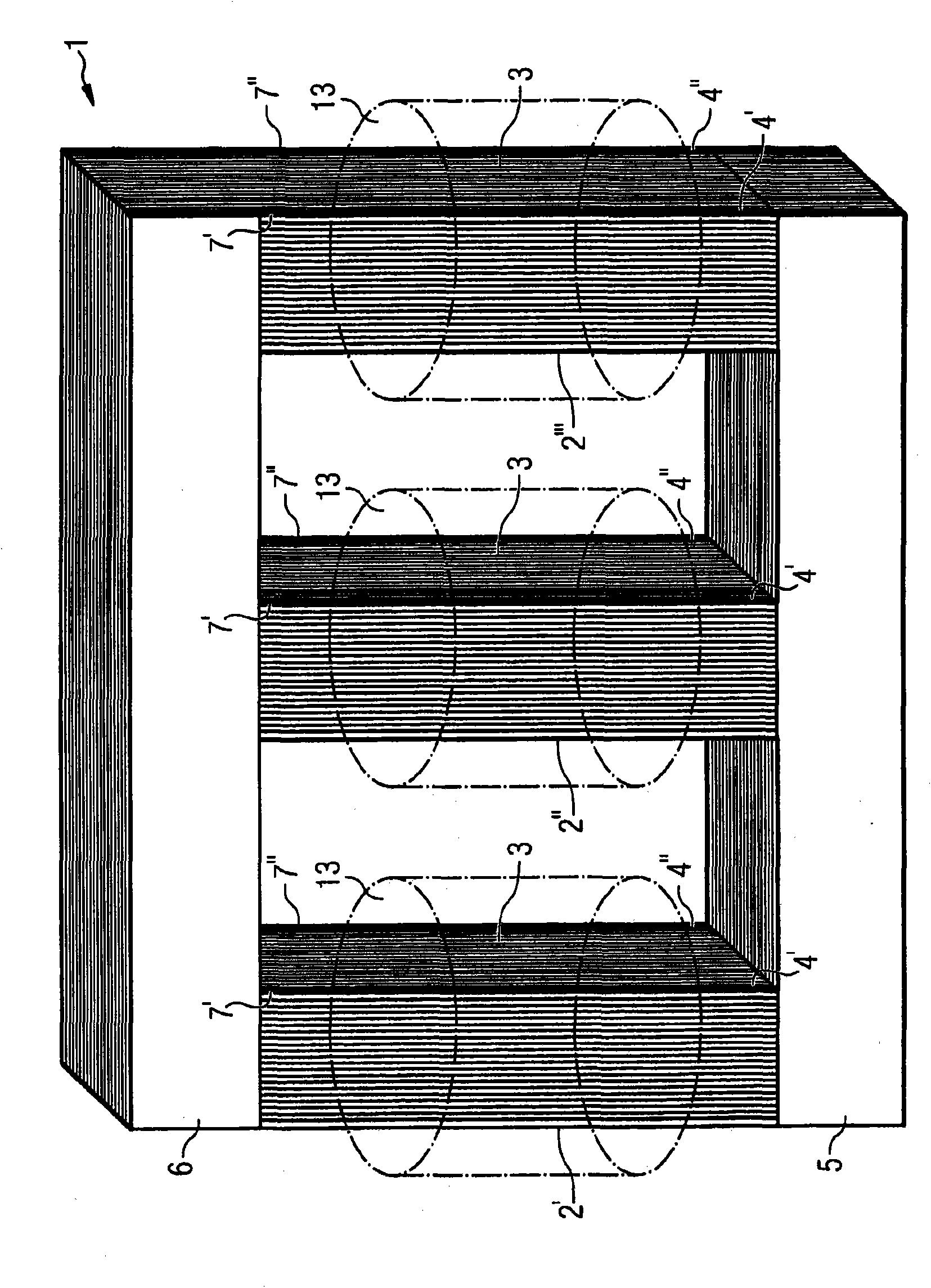
[0024] figure 1 The perspective view of FIG. 2 shows in diagram form a three-leg transformer known per se, the magnetic core 1 of which is made of sheet metal. The magnetic core 1 basically consists of three magnetic core legs 2 ′, 2 ″, 2 ′″, a lower yoke 5 and an upper yoke 6 . Each of the magnetic core legs 2', 2", 2'" carries a winding arrangement 13 which is figure 1 Indicated by the dotted line.

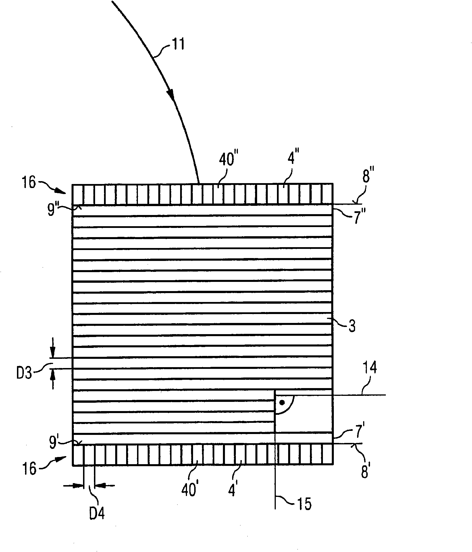
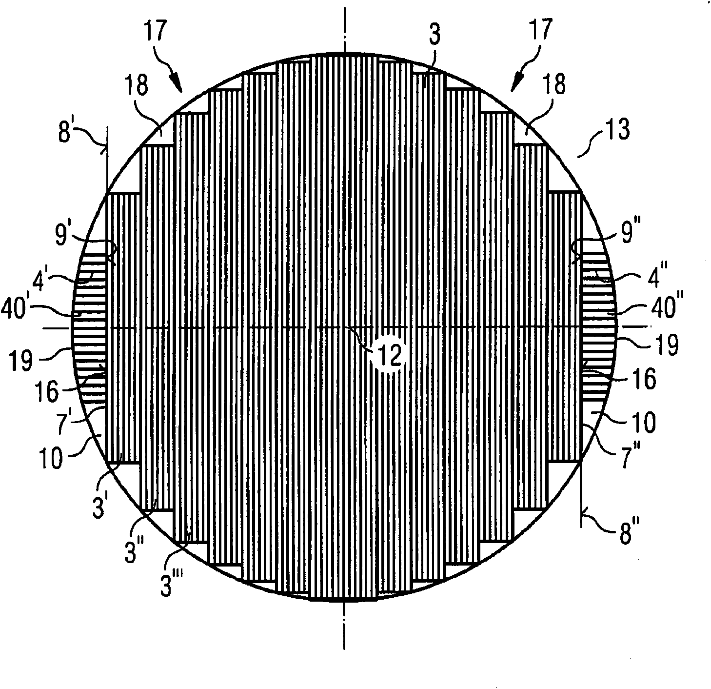
[0025] as from figure 1 As can also be seen in the spatial diagram of , each of the magnetic core legs 2', 2", 2'" is respectively composed of (magnetic core leg) laminations 3 and two additional laminations 4' and 4". As described in further detail below, the laminations 4', 4" act as leakage field shields. Viewed in the stacking direction, the laminated core 3 is closed at the end side by the end laminations 7', 7". figure 1 The front lamination group 4' abuts against the front end sheet layer 7' of the lamination group 3, and the rear lamination group 4" abuts agains...


PUM

PropertyMeasurementUnit
thicknessaaaaaaaaaa
thicknessaaaaaaaaaa

Abstract

The invention relates to a transformer core having a stray field shield, comprising at least one core leg (2', 2'', 2''') carrying a winding arrangement (13) and formed from a laminate stack (3), said laminate stack (3) being sealed by end plates (7', 7''), each end plate (7', 7'') being associated with a stray field shield (4', 4'') that comprises coated laminate plates (40', 40''), the layer planes (15) of which are disposed perpendicular to the layer planes (14) of the laminate stack (3), characterized in that the laminate plates (40', 40'') are disposed with laminate plate faces (9', 9'') pointing toward the laminate stack (3) to abut an exterior width surface (8', 8'') of an associated end plate (7', 7'').

Description

technical field [0001] The invention relates to a transformer core with stray field shielding, which has at least one core leg of a lamination pack carrying a winding arrangement, wherein the lamination pack is closed by end laminations, wherein A stray field shield (Streufeldschirm) is assigned to each end lamination, said stray field shield having stacked lamination laminations, the layer plane of which is arranged as a superposition with the magnetic core leg The layer plane of the slice group is vertical. Background technique [0002] In electric machines, machine parts such as the rotor of an electric motor, a transformer or the magnetic legs of an induction coil are implemented as being made of sheet metal. Eddy current losses induced by temporal changes in the magnetic flux can thus be kept low. In electrical machines, however, so-called leakage fluxes also occur, which, although always much smaller than the main flux guided in the machine parts, still likewise caus...

Claims


Application Information

Patent Timeline
Patent Type & Authority Applications(China)
IPC IPC(8): H01F27/245H01F27/36
CPCH01F27/245H01F27/365H01F27/263H01F27/36H01F27/366
Inventor P·哈姆伯格M·梅林格
Owner SIEMENS AG
Why Eureka
Try Eureka