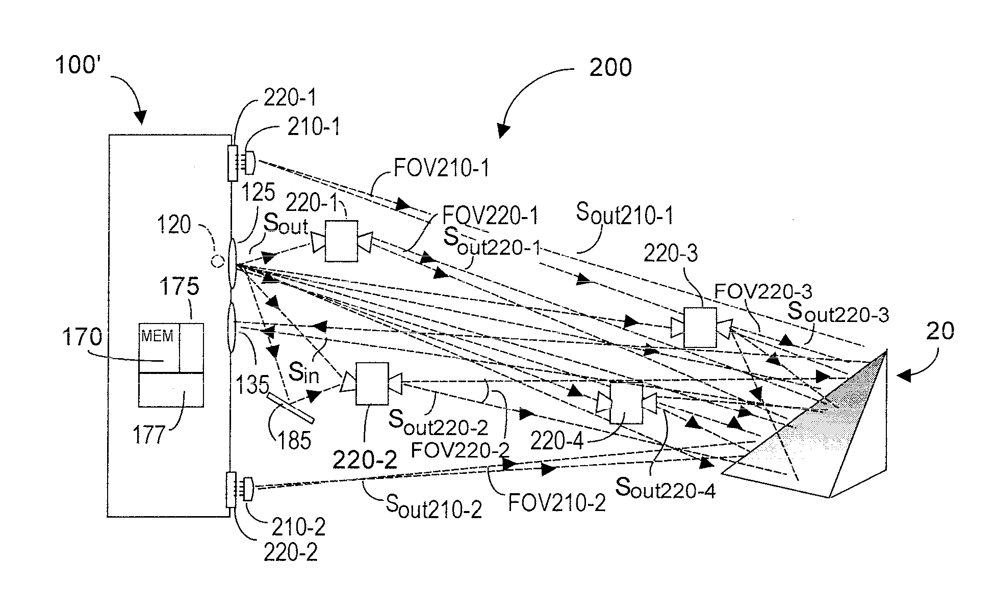
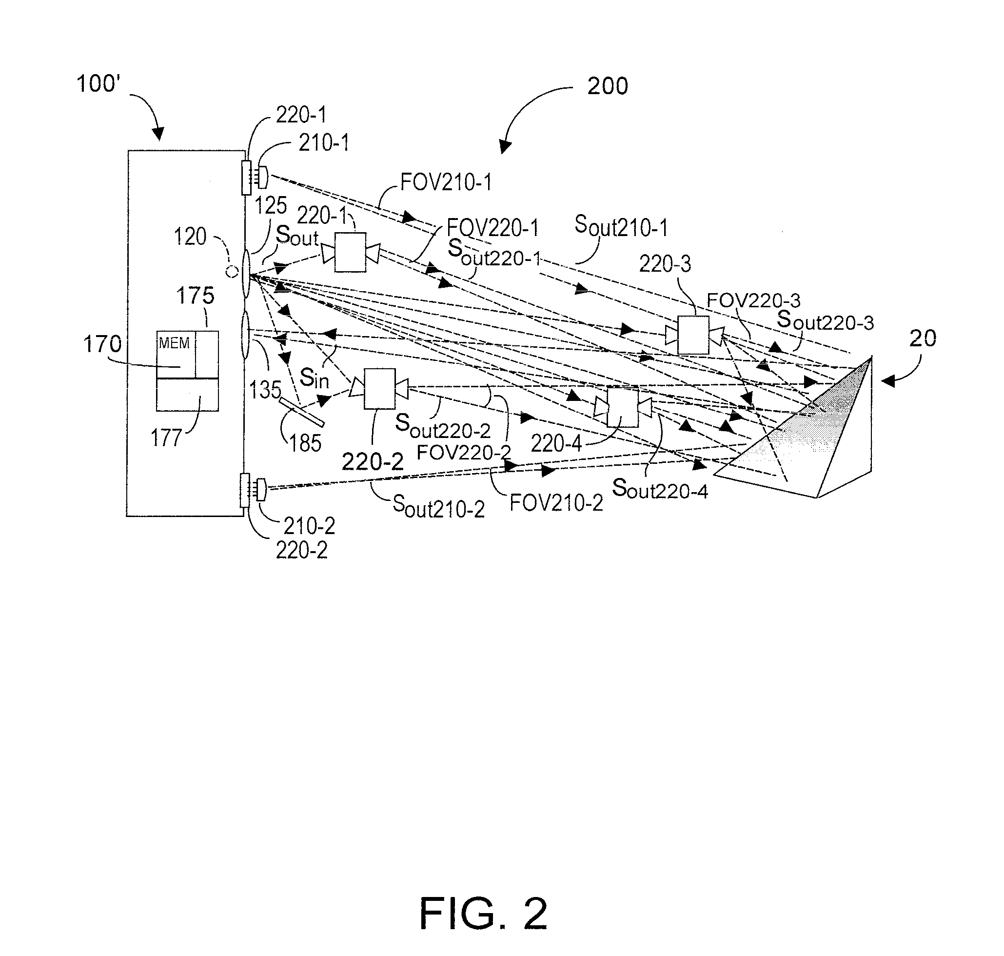
[0015]The present invention recognizes that in many applications it is desirable to augment the effective optical power emitted by a phase-based TOF system to direct more optical energy toward at least a region of the target object. Effective optical power augmentation is achieved in one embodiment by including at least one auxiliary wireless optical emitter (WOE) unit that is preferably optically and wirelessly dynamically synchronized in modulation frequency and in phase to the Sout emissions from the TOF system. The WOE units are disposed so as to illuminate at least a portion of the target object with their emitted optical energy. The optical power emitted by such units may be less than, greater than, or even the same as the Sout optical power emitted by the TOF system. An advantage of relatively low power WOE units is their reasonably small cost and form factor, and the ability to dispose them relatively close to the target object. The effective optical energy illumination provided by such unit(s) disposed close to the target object can be very substantial. Preferably each auxiliary optical emitter is a standalone unit, and may, but need not be, battery operated.
[0016]As noted, quality of the depth images acquired by the TOF system is a function of the incoming reflective Sin optical energy. Generation of proper depth images requires that all sources of Sout optical energy, i.e., the TOF system optical emitter and all WOEs, be dynamically synchronized both with respect to modulation frequency and phase relative to TOF system Sout emitted optical energy. Preferably each WOE unit includes a first optical sensor responsive to incoming Sout optical energy emitted by the TOF system, an optical emitter that outputs optical energy, a free running voltage controlled oscillator (VCO) nominally operating at the frequency of the TOF oscillator, a second optical sensor responsive to optical energy emitted by the WOE, and a preferably phase lock loop (PLL) system operating in closed loop feedback to force frequency and phase of the optical energy emitted by the WOE to match that of the incoming TOF optical energy Sout. Within each WOE the frequency of the VCO is dynamically synchronized to the TOF system Sout frequency using preferably PLL circuitry, and frequency synchronization is confirmed by sampling the WOE unit emitted optical energy. The phase of the WOE unit emitted optical energy is synchronized with the TOF system Sout phase, and phase synchronization is confirmed by sampling the WOE unit emitted optical energy. Preferably, the first optical sensor and the optical emitter in each WOE unit is mechanically swivelable, so as to better detect incoming Sout optical energy, and to better direct the unit's emitted optical energy toward the target object. Preferably software executed within the TOF system, preferably with hardware support, can disregard initial time regions of Sin signals, during which time regions synchronization lock is not yet attained. In addition, software executed within the TOF system can intelligently assist, as needed, in processing Sin information, taking into account, as needed, time needed to dynamically lock frequency and phase for the WOE units, FOV, output power, and other characteristics of individual WOE units. Preferably memory within each WOE unit can store the most recently PLL synchronization parameters to potentially hasten re-synchronization as Sout optical energy changes in frequency and / or phase.
[0017]In a second embodiment, at least one auxiliary plug-wired optical emitter (PWOE) unit is physically removably attachable to the housing of the TOF system, preferably by a plug connection whose short wire length minimizes propagation delay. The plug connection enables a very short wire length to couple this PWOE to the drive signal to the TOF primary optical emitter. Circuitry within the TOF system examines the delay lag in an image acquired solely using each such PWOE unit, one at a time, and compares to an image acquired solely using the TOF primary optical emitter. The TOF system circuitry can compensate for the delay lag associated with data acquired using optical energy from each PWOE unit used in isolation and without optical energy from the primary optical unit. Alternatively, the TOF circuitry can tune the delay of each PWOE to match the delay of the primary optical unit. Any number of the thus properly delay-compensated or selected PWOE(s) can then be used in parallel with the TOF system primary optical source to increase the amount of optical energy falling upon the target object. A TOF system may employ at least one WOE and at least one PWOE unit, if desired.

