Mechanical ventilation system utilizing bias valve

a mechanical ventilation and bias valve technology, applied in the field of mechanical ventilators, can solve the problems of inability to accurately measure the flow output of the ventilator, the efficiency of the ventilator is typically low, and the prior art mechanical ventilators have not been truly portable devices. achieve the effect of viscous damping and accurate measurement of the flow outpu

Active Publication Date: 2006-11-09
VYAIRE MEDICAL 203 INC
View PDF99 Cites 99 Cited by
  • Summary
  • Abstract
  • Description
  • Claims
  • Application Information

AI Technical Summary

Benefits of technology

[0015] Viscous damping is provided by the poppet as it reciprocates within the cylinder. More specifically, an annular poppet clearance located between the poppet and the cylinder results in the creation of the viscous damping which occurs when gas trapped at the bottom of the cylinder passes through the poppet clearance as the poppet moves downward into the cylinder. Conversely, gas must pass through the poppet clearance in reverse direction in order to fill the expanding volume at the bottom of the cylinder as the poppet moves out of the cylinder. The passage of the gas through the poppet clearance creates the viscous damping effect. Advantageously, the combined effects of the viscous and inertial damping are preferably sufficient to attenuate the pulsating flow output produced by the Roots blower such that the flow meter may accurately measure flow output therefrom.

Problems solved by technology

Unfortunately, such mechanical ventilators have traditionally been configured as relatively large devices which occupy a relatively large volume of the limited space available in operating rooms and patient recovery rooms.
In addition, such prior art mechanical ventilators are typically of low efficiency such that relatively large amounts of power are required in order to operate the device.
In addition, mechanical ventilators of the prior art have not been truly portable devices in that such devices must typically be continuously connected to a main power supply during operation.
The relatively large weight and bulk of such devices further limits their portability.
Unfortunately, such rapid acceleration and deceleration necessitates complex drive circuitry for the compressor and consumption of high electrical currents.
The relatively high current draw of such variable speed drag compressors increases the overall cost of the mechanical ventilator.
Furthermore, the high current requirement necessitates the incorporation of bulky and heavy batteries for providing standby battery power as an emergency back-up when the ventilator is not connected to a stationary power source.
Unfortunately, such constant speed drag compressors possess their own set of inherent deficiencies which detract from the overall utility of the mechanical ventilator.
Although the power consumption may be reduced by recirculating the air flow during exhalation to an intake of the compressor, a considerable amount of standby battery power is still required to operate the mechanical ventilator when not connected to a stationary power source.

Method used


Image

  • Mechanical ventilation system utilizing bias valve
  • Mechanical ventilation system utilizing bias valve
  • Mechanical ventilation system utilizing bias valve

Examples


Embodiment Construction

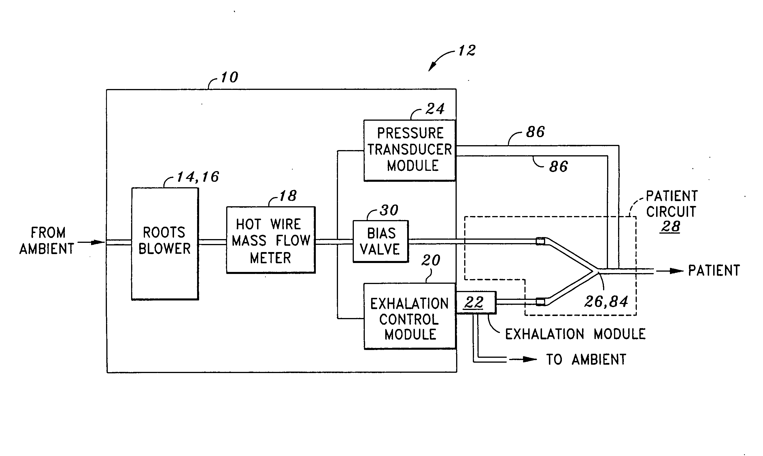
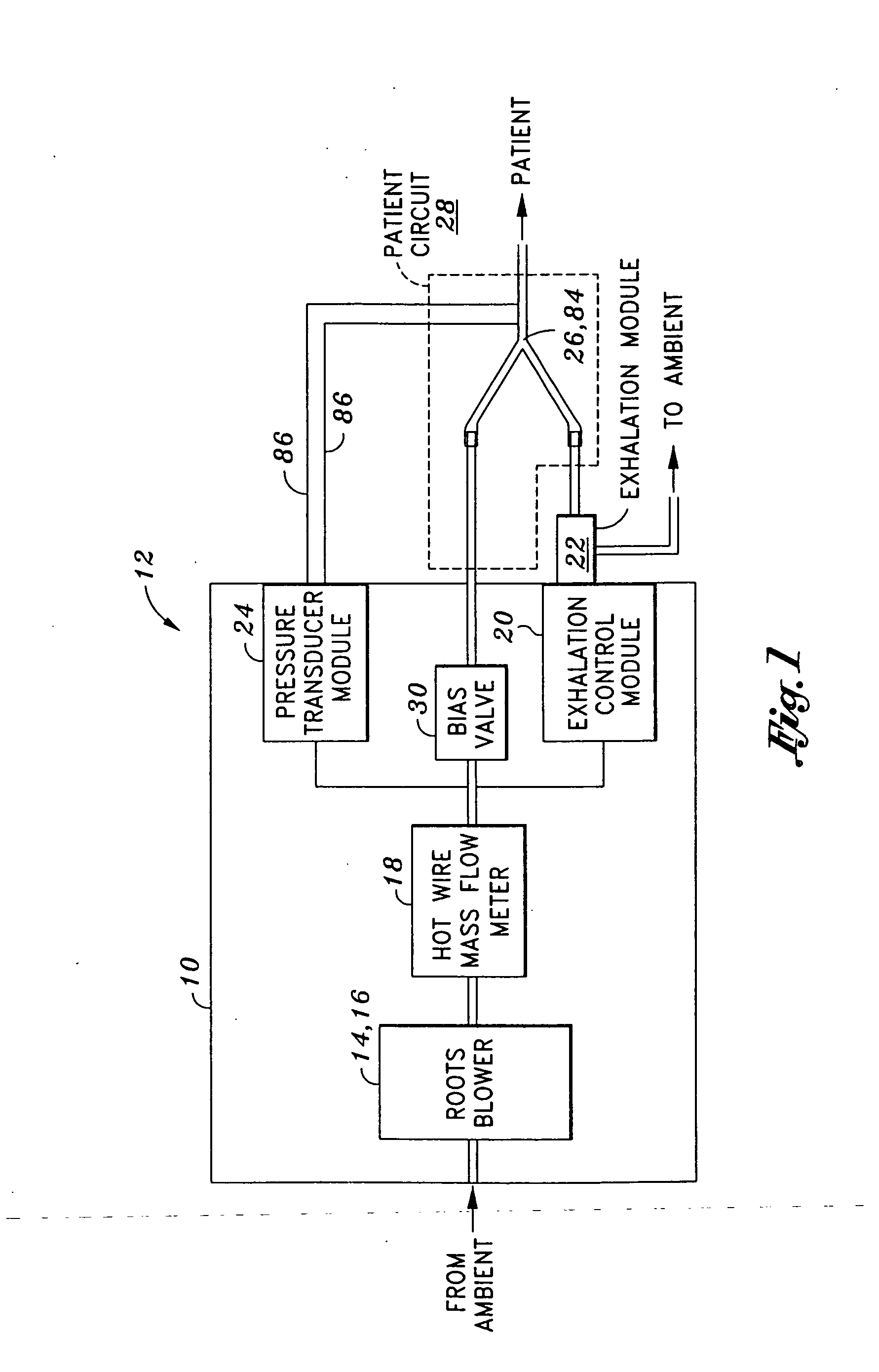
[0021] Referring now to the drawings wherein the showings are for purposes of illustrating the present invention and not for purposes of limiting the same, shown is a portable mechanical ventilator 10 having a blower assembly 14 such as a Roots blower 16 for producing gas flow to a patient or patient circuit 28 via a patient connection 26. As is described in greater detail in U.S. Patent Publication No. 2005 / 0051168 entitled PORTABLE VENTILATOR SYSTEM to DeVries et al., the entire contents of which is expressly incorporated by reference herein, the portable ventilator 10 operates in variable speed mode as the breath delivery mechanism and has improved efficiency and reduced size resulting from the use of the Roots blower 16.

[0022] The portable mechanical ventilator 10 preferably includes sound-reducing elements to facilitate operation thereof in noise-sensitive environments such as in a patient-recovery room of a hospital. Furthermore, the portable mechanical ventilator 10 has redu...


PUM


Abstract

A portable mechanical ventilator having a Roots blower is configured to provide a desired gas flow and pressure to a patient circuit. The mechanical ventilator includes a flow meter operative to measure gas flow produced by the Roots blower and an exhalation control module configured to operate an exhalation valve connected to the patient circuit. A bias valve connected between the Roots blower and the patient circuit is specifically configured to generate a bias pressure relative to the patient circuit pressure at the exhalation control module. The bias valve is further configured to attenuate pulsating gas flow produced by the Roots blower such that gas flowing to the mass flow meter exhibits a substantially constant pressure characteristic. The bias pressure facilitates closing of the exhalation valve at the start of inspiration, regulates positive end expiratory pressure during exhalation, and purges sense lines via a pressure transducer module.

Description

CROSS-REFERENCE TO RELATED APPLICATIONS [0001] This application is a continuation-in-part of U.S. patent application Ser. No. 10 / 912,747 filed Aug. 4, 2004, and claims the benefit of priority from U.S. Provisional Patent Application No. 60 / 492,421 filed Aug. 4, 2003, U.S. patent application Ser. No. 10 / 847,693 filed May 18, 2004, U.S. patent application Ser. No. 10 / 912,747 filed Aug. 4, 2004, U.S. patent application Ser. No. 10 / 985,528 filed Nov. 10, 2004, U.S. patent application Ser. No. 11 / 088,316 filed Mar. 23, 2005, and U.S. patent application Ser. No. 11 / 234,636 filed Sep. 23, 2005, the specifications and figures of all of which are expressly incorporated by reference herein.STATEMENT RE: FEDERALLY SPONSORED RESEARCH / DEVELOPMENT [0002] Not Applicable BACKGROUND [0003] The present invention relates generally to mechanical ventilators and, more particularly, to a portable ventilator that incorporates a low-inertia, high speed, high efficiency Roots-type blower that is specificall...

Claims


Application Information

Patent Timeline
Patent Type & Authority Applications(United States)
IPC IPC(8): A61M16/00A62B9/02A62B7/00F01C1/18
CPCA61M16/0057A61M16/0066A61M16/208A61M2016/0021A61M2016/0039A61M16/205F04C18/126F04C28/24F04C29/0035F04C2220/24A61M16/0833A61M2205/42A61M16/0003A61M16/0069A61M16/107A61M2016/003A61M2205/3334
Inventor DEVRIES, DOUGLAS F.ALLUM, TODD
Owner VYAIRE MEDICAL 203 INC
Why Eureka
Try Eureka