Digital polarimetric system

Inactive Publication Date: 2005-06-28
EXCELIS INC
View PDF11 Cites 110 Cited by
  • Summary
  • Abstract
  • Description
  • Claims
  • Application Information

AI Technical Summary

Benefits of technology

[0011]Therefore, in light of the above, and for other reasons that become apparent when the invention is fully descri

Problems solved by technology

Thus, conventional polarimeters are bulky, heavy and costly devices that dissipate as much as fifty percent of the RF signal power, adversely affecting the EW system performance.
Consequently, the traditional polarimeter design is not affordable for many small or low-cost EW systems.
These hybrid junctions may permit some degree of RF cross leakage to corrupt the combined signals, thereby complicating the task of achieving a deep null and limiting performance of the analog polarimeter.
Moreover

Method used


Image

  • Digital polarimetric system
  • Digital polarimetric system
  • Digital polarimetric system

Examples


Example

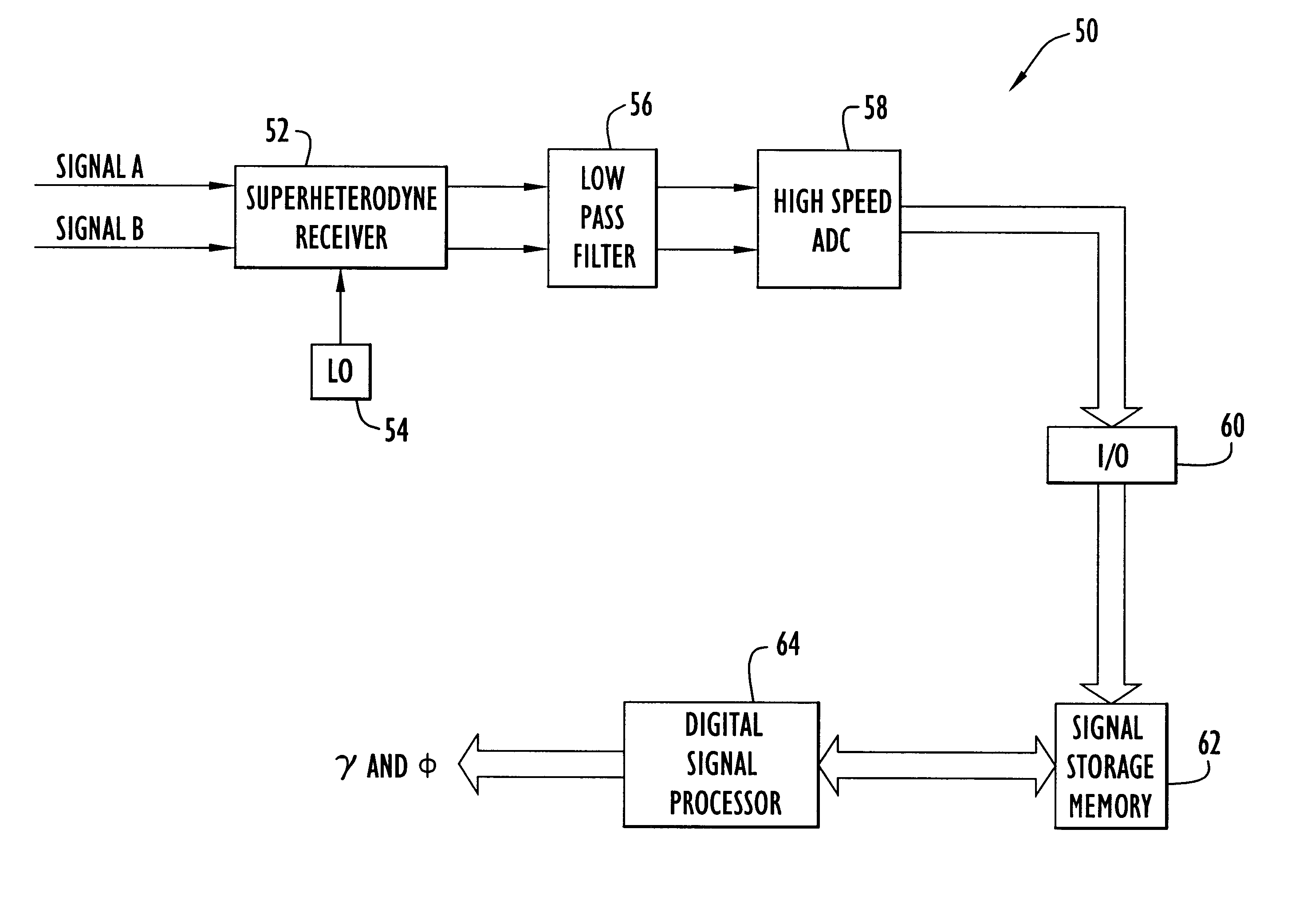
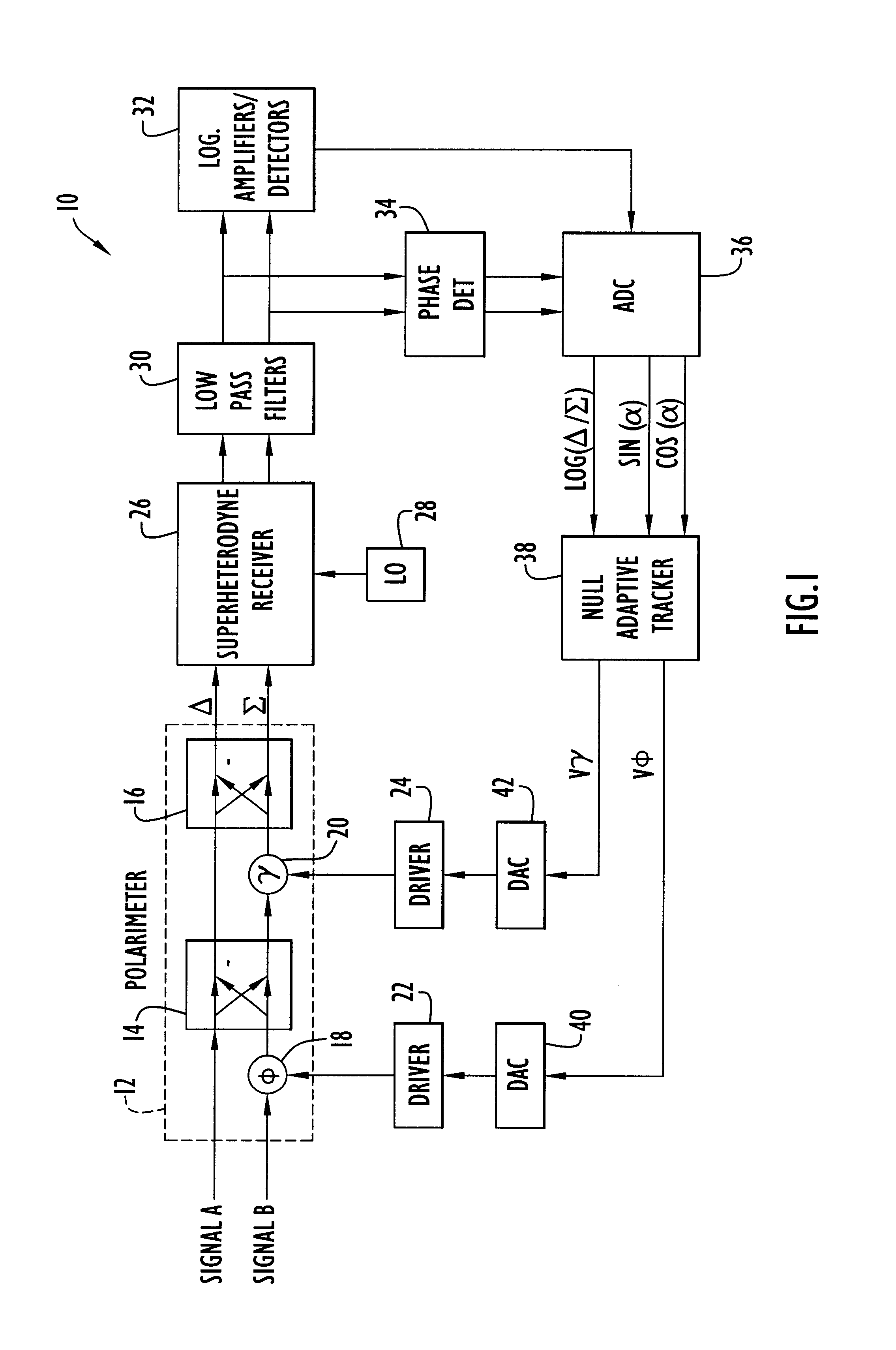
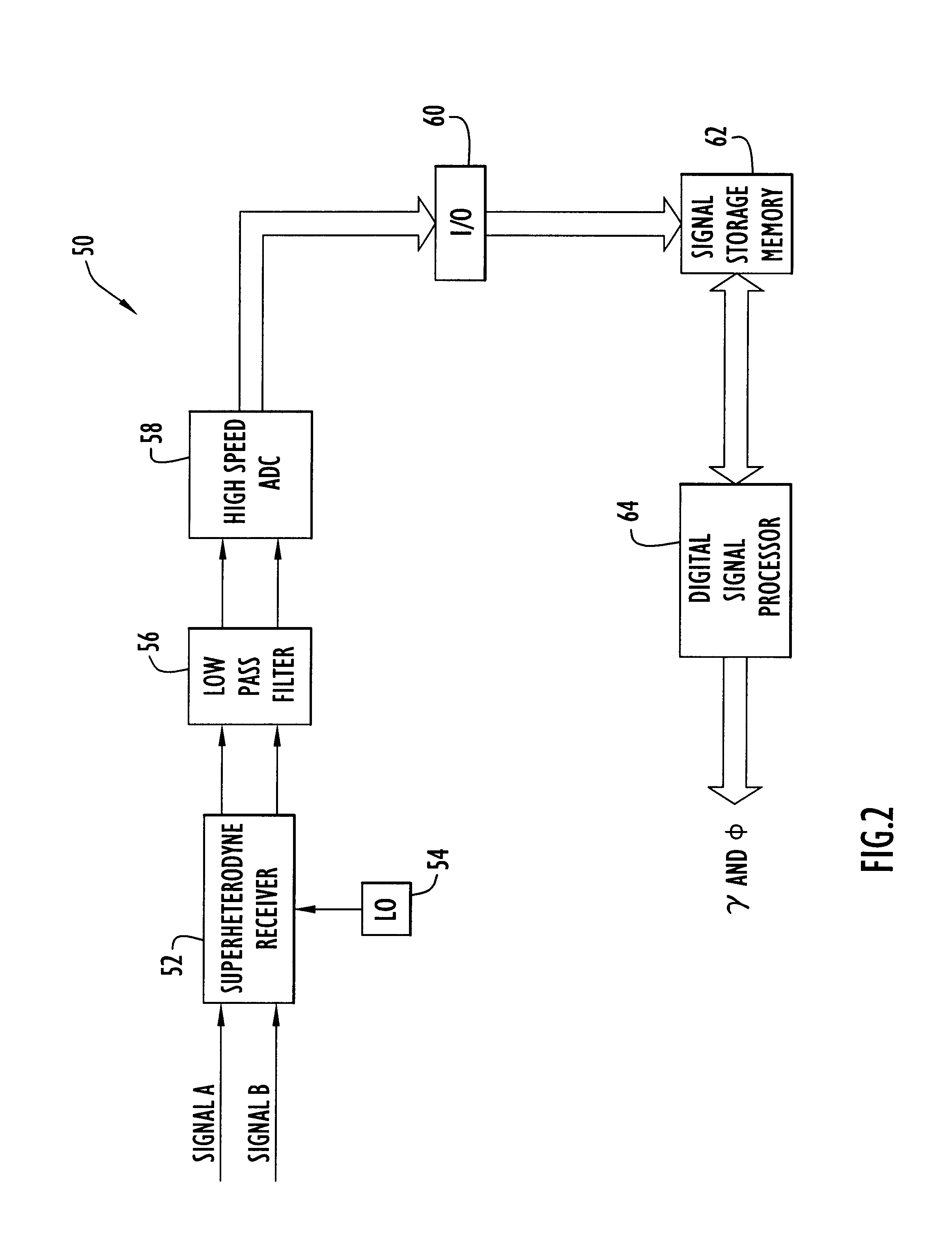
[0030]The following detailed explanations of the figures and of the preferred embodiments reveal the methods and apparatus of the present invention. A general null adaptive polarization tracking technique is described in connection with the block diagram of an analog polarimetric system 10 employing a feedback loop shown in FIG. 1. System 10 includes an analog polarimeter 12 which separately receives the horizontal component (signal A) and the vertical component (signal B) of a received signal, such as series of radar pulses. The perceived polarization of a received radar signal is a function of the orientation of the antenna of the EW system; thus, the portion of the received signal constituting the “horizontal” component and the portion constituting the “vertical” component is dependent upon the present orientation of the EW antenna. For example, an airborne EW system will typically receive a vertically polarized signal from a ground-based radar. How the EW antenna “sees” this ver...


PUM


Abstract

A digital polarimeteric system employs a signal time stretching technique and digital signal processing of the time-stretched signal to accurately measure the polarization of a received RF signal with commercially available digital hardware. A superheterodyne receiver down converts received RF signal components to IF, and analog-to-digital converters sample the signal components at much lower sampling rates than would normally be required to accurately measure the signal polarization. Each signal sample is “time stretched” by storing each sample in M locations in a memory, such that N samples occupy M×N memory locations. A digital signal processor applies incremental phase shifts to the digital samples until a phase-shifted combination of the digital samples yields a minimum null output. The phase shifts producing the minimum null identify the polarization of the received signal. The stretching and digital processing yield the required number of samples per cycle of the received signal for accurate polarization measurement, thus effectively increasing the digital sampling frequency. Because each sample is stored in M memory locations, each incremental phase shift corresponds to 1/Mth of the actual sampling interval, thereby providing the high phase resolution required to accurately measure polarization.

Description

CROSS REFERENCE TO RELATED APPLICATION[0001]This application claims priority from U.S. Provisional Patent Application Ser. No. 60 / 164,947 entitled “Digital Polarimetric System,” filed Nov. 12, 1999. The disclosure of this provisional patent application is incorporated herein by reference in its entirety.BACKGROUND OF THE INVENTION[0002]1. Field of the Invention[0003]The present invention relates to electronic warfare (EW) systems that use polarimeters to measure polarization of a received radar signal and to transmit electronic counter measures (ECM) signals with a preferred polarization and, more particularly, to a digital implementation of such a polarimeter.[0004]2. Description of the Related Art[0005]Ground-based and airborne radar systems have long been used to detect and track hostile targets, such as aircraft and missiles. Typically, a radar system transmits RF signals, such as a sequence of pulses, toward the target. The surface of the target reflects at least some portion o...

Claims


Application Information

Patent Timeline
IPC IPC(8): G01S13/00G01S7/02G01S7/292
CPCG01S7/2921G01S7/024
Inventor SPARROW, MITCHELL J.CIKALO, JOSEPH
Owner EXCELIS INC
Why Eureka
Try Eureka