Apparatus for heating fluids

Inactive Publication Date: 2012-11-22
CAVITATION HLDG LLC
View PDF6 Cites 17 Cited by
  • Summary
  • Abstract
  • Description
  • Claims
  • Application Information

AI Technical Summary

Benefits of technology

[0012]It is therefore an object of the present invention to provide a device for heating a fluid using a rotor and a stationary housing, which device is structurally simple with reduced manufacturing and maintenance costs. Maintenance costs are reduced because, in one preferred embodiment, seals are located on only one side of the generator. Mechanical seals typically are the most maintenance-intensive components of the system, requiring frequent repl

Problems solved by technology

In dairy production, cavitation-induced heating results in reduced maintenance, since pasteurization would occur without direct contact between the milk and a heat exchanger surface.
The water used to fracture natural gas bearing rock, or “frac water”, is usually contami

Method used


Image

  • Apparatus for heating fluids
  • Apparatus for heating fluids
  • Apparatus for heating fluids

Examples


Example

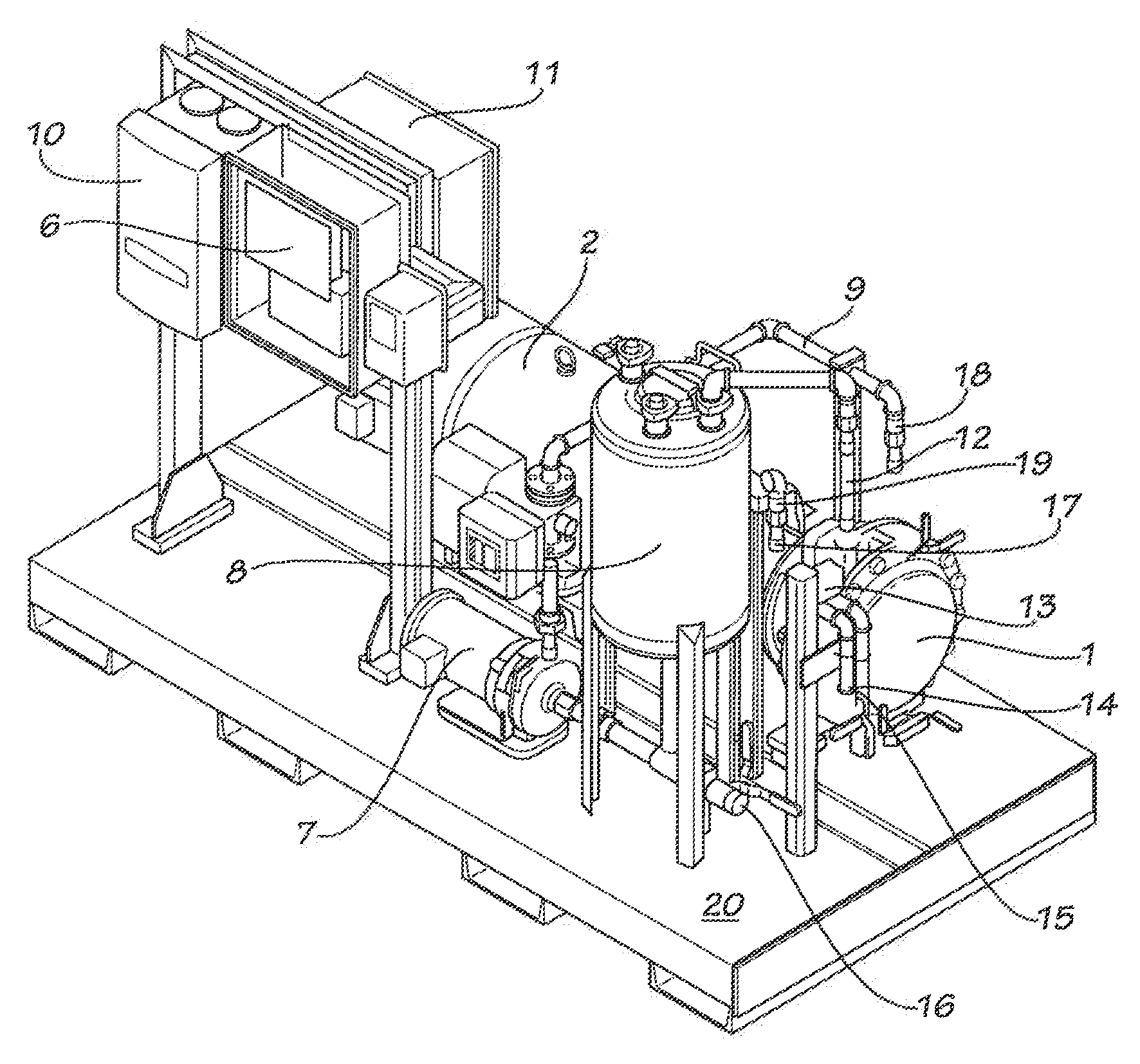
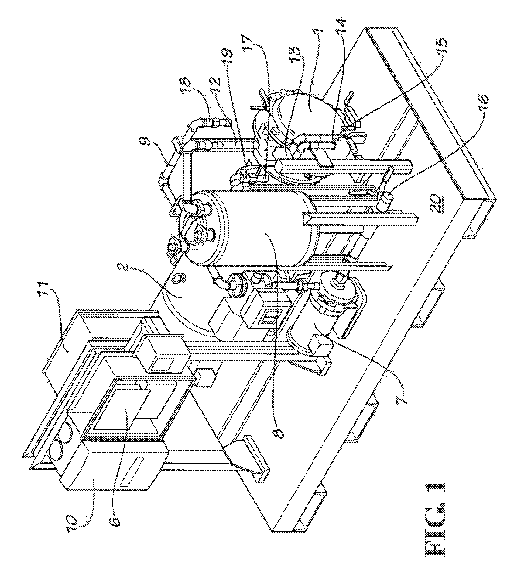
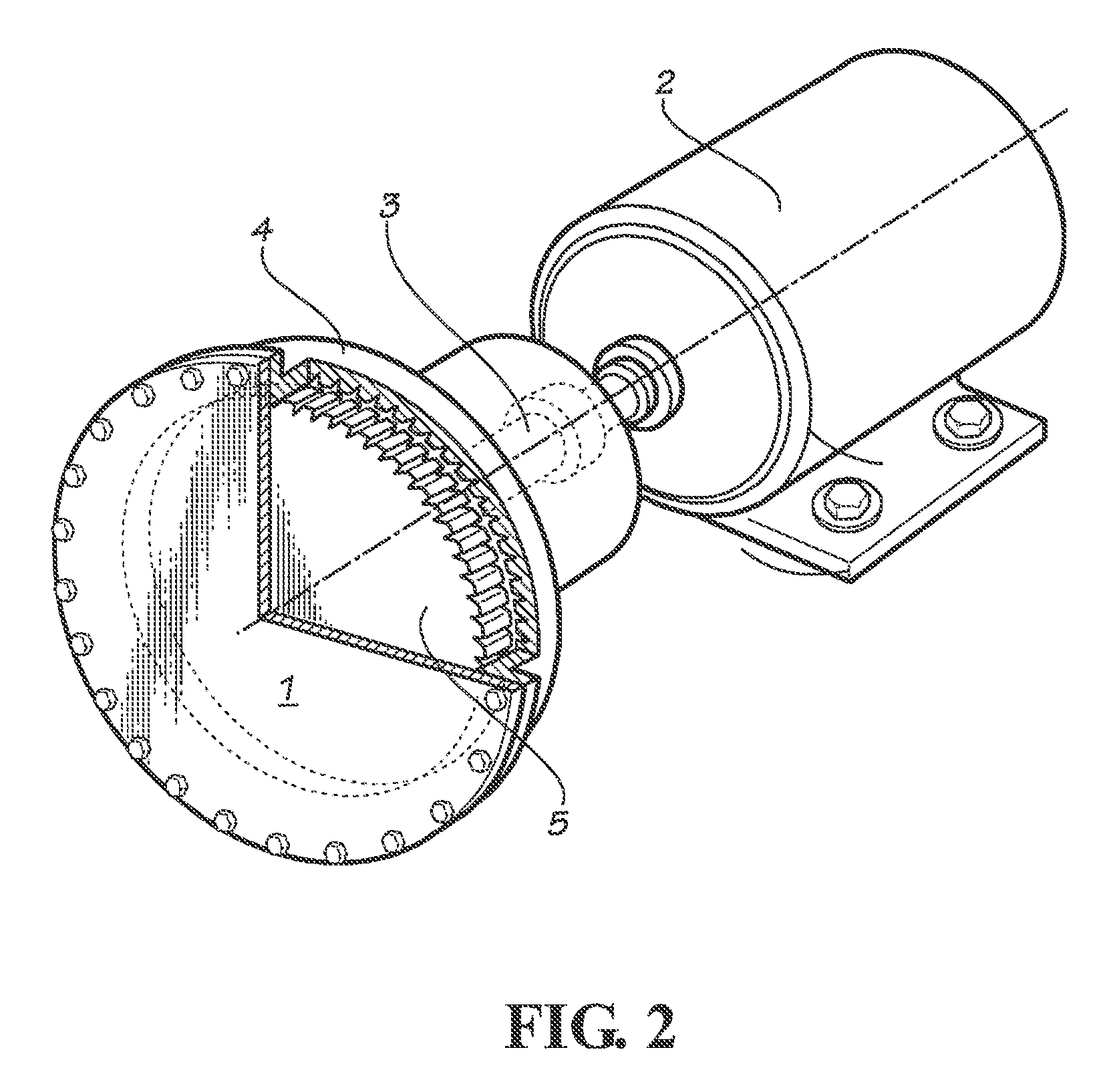
[0023]FIG. 1 shows the overall configuration of the preferred embodiment of a system 20 designed to purify contaminated water, such as frac water, in batches. The contaminated fluid is first pumped into tank 8. From the tank, the fluid passes through tank outlet line 17 to the inlet of cavitation generator 1. As shown in FIG. 2 and as described above, the cavitation generator consists of two primary parts, a rotor housing 4 and a rotor 5. The rotor 5 is driven by a shaft 3 that is coupled to a motor 2. In the preferred embodiment, an electric motor is used. The size of the motor is dependent on the size of the unit; typically, 500 or 1000 horsepower motors would be used for applications requiring purification of up to 100,000 gallons per day. One skilled in the art will realize that any type of motive power capable of providing torque to a shaft can be substituted for an electric motor, although in these cases additional mechanical complexity may be required in the form of gears to ...


PUM


Abstract

The apparatus described herein uses a disc wafer-type rotor featuring channels disposed around its circumference and around the interior circumference of the rotor housing specifically to induce cavitation. The channels are shaped to control the size, oscillation, composition, duration, and implosion of the cavitation bubbles. The rotor is attached to a shaft which is driven by external power means. Fluid pumped into the device is subjected to the relative motion between the rotor and the device housing, and exits the device at increased temperature. The device is thermodynamically highly efficient, despite the structural and mechanical simplicity of the apparatus. Such devices accordingly provide efficient, simple, inexpensive, and reliable sources of distilled potable water for residential, commercial, and industrial use, as well as the separation and evaporation of other liquids.

Description

CROSS REFERENCE TO RELATED APPLICATIONS[0001]This application claims priority to provisional patent application Ser. No. 61 / 488,061 filed May 19, 2011 under 35 U.S.C. §119(e).BACKGROUND OF THE INVENTION[0002]The present invention is an apparatus for heating liquids using a rotor and housing featuring indentations therein that induce cavitation bubbles in the liquid. The heat generated when these bubbles rapidly collapse is transferred to the fluid. Thus, the apparatus permits efficient heat transfer to a fluid without a solid heat exchanger interface.[0003]There are a variety of patented devices (see table below) that use mechanical energy to increase the temperature and / or pressure of fluids. Some of these prior art devices heat the fluid through friction between the fluid and the walls of a rotor and housing. In other prior art designs, mechanical agitation of the liquid generates heat. The '349 patent to Schaefer discloses an apparatus to produce steam pressure by inducing shock ...

Claims


Application Information

Patent Timeline
IPC IPC(8): F24H9/00
CPCF24H9/00C02F1/36C02F2103/365C02F2101/32C02F1/78F24D2200/30F24V40/00B01D1/0011C02F1/043C02F2103/10F22B3/06
Inventor GRIGGS, JIM
Owner CAVITATION HLDG LLC
Why Eureka
Try Eureka