Flow conditioner and method for optimization

a flow conditioner and optimization technology, applied in the field of flow conditioners, can solve problems such as inability to adapt to the requirements, affecting the calibration or flow coefficient of certain types of flow meters, and inability to meet the requirements

Active Publication Date: 2016-11-29
CAMERON FLOW CONTROL TECH UK +1
View PDF11 Cites 5 Cited by
  • Summary
  • Abstract
  • Description
  • Claims
  • Application Information

AI Technical Summary

Benefits of technology

[0015]The flow conditioner of the current invention is based on an arrangement of segmented annular passages, arranged symmetrically around the center-line of a circular conduit. The choice of segmented annular passages allows the cross-sectional area of the pipe to be divided into a predetermined number of annular rings with the width and separation of the passages to be freely varied in both radial and tangential directions, to obtain a desired value of hydraulic diameter and porosity in each ring. Combined with control over the length of the passages via selecting the thickness of the conditioner, this arrangement of segmented annular passages can be optimized to produce a conditioner which will retard swirl and have a desired radial distribution of resistance, in combination with a specified overall pressure loss.

Problems solved by technology

It is well known that the calibration or flow coefficient of certain types of flow meter is affected by distortions of the profile and / or by the presence of swirl.
The various devices deployed to date differ in design with resulting differences in performance in terms of their ability to rectify flow versus the permanent pressure loss that they impose.
Most conditioners have a single specified geometry or a constrained set of design parameters and cannot easily be adapted to suit the requirements of a particular situation.
A recognized deficiency of the tube bundle design of flow conditioner is that while it is effective at removing swirl, the emerging axial velocity profile does not tend to be fully developed, that is it generally tends to be flatter than the profile that would be found downstream of a long straight length of pipe at the Reynolds number of interest.
A disadvantage of this conditioner design in terms of manufacturing, which also applies to most tube bundle designs, is that when pipe diameter is varied, the required tube diameters may not be readily available in standard sizes of tubing.
A further disadvantage of the tube bundle is its variable design and quality.
If not constructed to the ISO standard, the potential variations in number and size of tubes are almost endless, making it difficult to predict performance or relate experience from one design of tube bundle to another.
However, it is somewhat difficult to manufacture and has a high pressure loss coefficient of greater than 5.
These thick-plate conditioners with circular passages are considered the current state-of-the-art but still have certain deficiencies.
Attempts to produce plates of higher porosity and hence lower pressure loss have generally resulted in a reduction in flow conditioning performance.
Optimization of the design of a thick-plate conditioner with circular passages is complicated by particular issues associated with the chosen circular hole geometry.
An irregular numbers of holes and the circular shape of the passages result in a complex ‘water-shed’ between adjacent rings of holes, and hence makes the calculation of the effective porosity difficult as the water-shed defines the blockage area associated with each hole.
Optimization is further complicated in cases where the circular passage size is varied, as for a given thickness of plate as this results in variation of both the porosity and the ratio of the length of the passage to its hydraulic diameter.
As mentioned previously, the effectiveness of thick-plate conditioners has been found to diminish when the porosity is increased too much, with the result that most thick-plate conditioners in use today have porosity in the region of 50%.
When porosity has been increased, the investigators have not tended to increase plate thickness to compensate for the reduction in l / d, which may partly explain the diminished performance.
However, this does not offset three of the disadvantages of tube bundles: first, that they alter the axial velocity profile in an adverse way; secondly the fact that they are generally manufactured to be between 2 and 3 diameters long, and thirdly the manufacturing issues mentioned above that can result in poor quality conditioners.

Method used


Image

  • Flow conditioner and method for optimization
  • Flow conditioner and method for optimization
  • Flow conditioner and method for optimization

Examples


Embodiment Construction

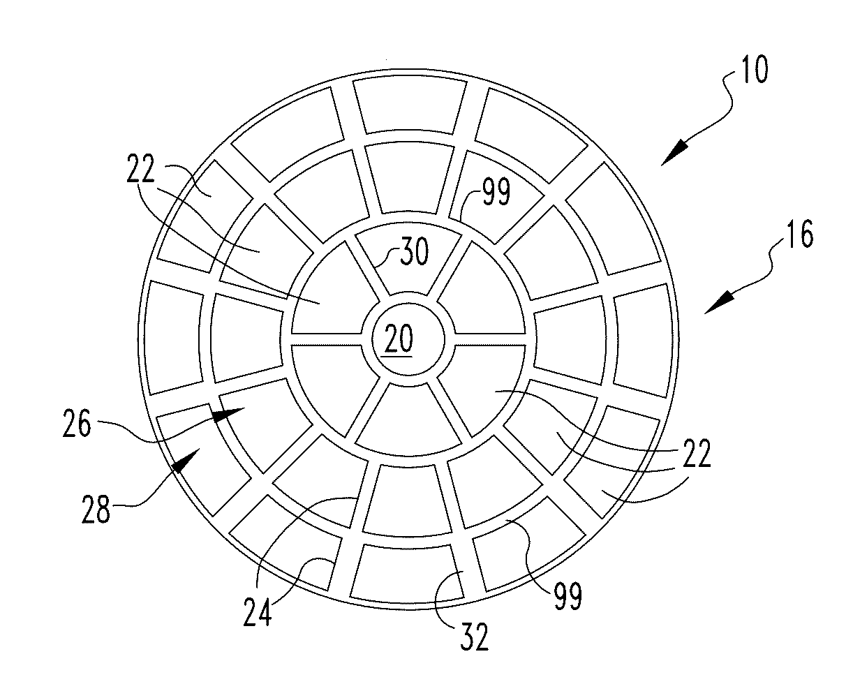
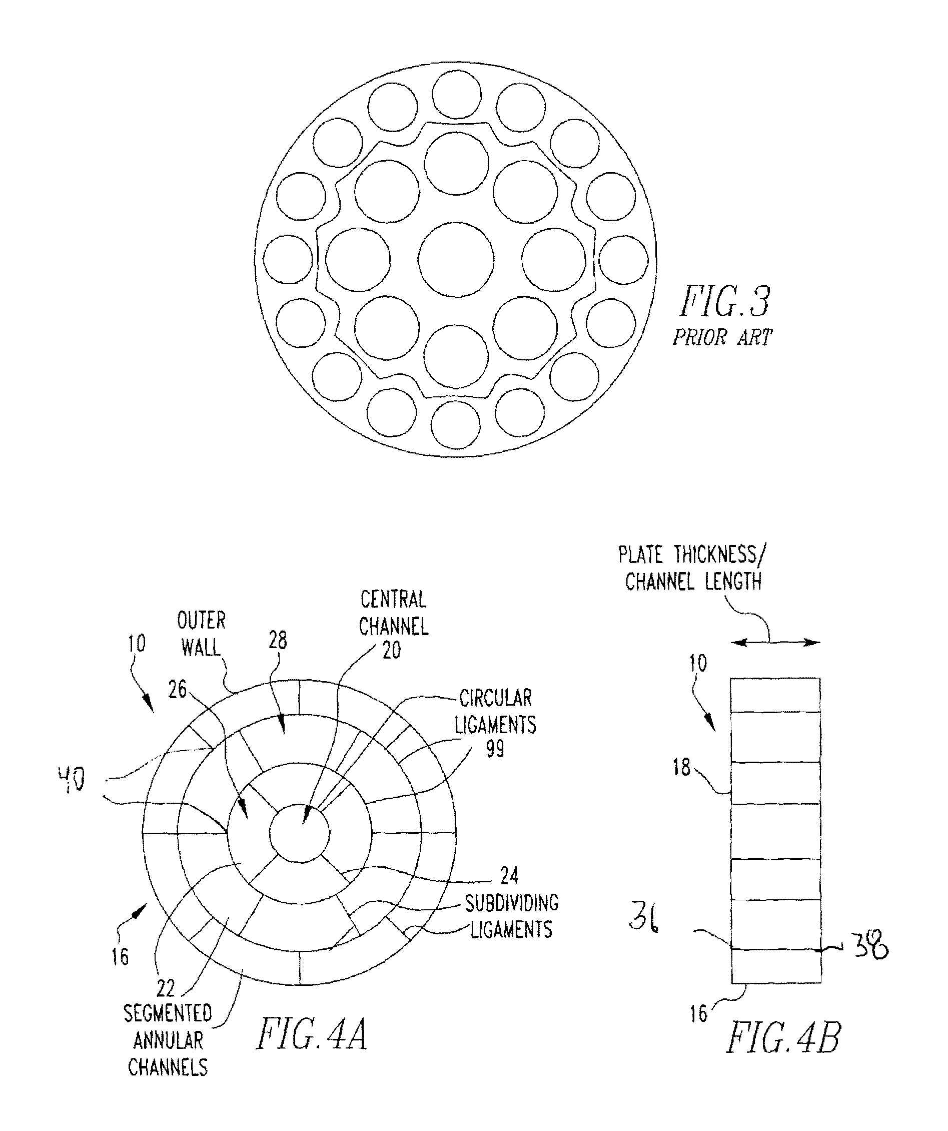
[0038]Referring now to the drawings wherein like reference numerals refer to similar or identical parts throughout the several views, and more specifically to FIGS. 4a and 4b thereof, there is shown a flow conditioner 10 for a circular pipe 12 having an axis 14. The flow conditioner 10 comprises a plate 16 having a face 18 to be disposed in the circular pipe 12 with the face 18 of the plate 16 perpendicular to the axis 14 of the pipe 12. The plate 16 has a central circular passage area 20 through which fluid flows surrounded by two or more concentric arrays of segmented annular passages 22 for fluid flow defined by separating and subdividing ligaments 24, with at least one array 26 of annular passages 22 having a radial width different than a radial width of a second array 28 of annular passages 22.

[0039]With reference to FIGS. 5a-5c, 7, 9a and 9b, the plate 16 may have at least one subdividing ligament 30 having a width different than a width of a second subdividing ligament 32. Th...


PUM


Abstract

A flow conditioner for a circular pipe having an axis. The flow conditioner includes a plate having a face to be disposed in the circular pipe with the face of the plate perpendicular to the axis of the pipe. The plate has a central circular passage area through which fluid flows surrounded by two or more concentric arrays of segmented annular passages for fluid flow defined by separating and subdividing ligaments, with at least one subdividing ligament having a width different than a width of a second subdividing ligament. Alternatively, or in addition, there is at least one array of annular passages having a radial width different than a radial width of a second array of annular passages and at least one subdividing ligament having a width different than a width of a second subdividing ligament. A method of producing an optimized geometry of flow conditioner for a circular pipe having an axis.

Description

FIELD OF THE INVENTION[0001]The present invention is related to a flow conditioner for flow regarding a flow metering device. (As used herein, references to the “present invention” or “invention” relate to exemplary embodiments and not necessarily to every embodiment encompassed by the appended claims.) More specifically, the present invention is related to a flow conditioner for a flow metering device where the conditioner has a central circular passage area through which fluid flows surrounded by two or more concentric arrays of segmented annular passages for fluid flow defined by separating and subdividing ligaments.BACKGROUND OF THE INVENTION[0002]This section is intended to introduce the reader to various aspects of the art that may be related to various aspects of the present invention. The following discussion is intended to provide information to facilitate a better understanding of the present invention. Accordingly, it should be understood that statements in the following ...

Claims


Application Information

Patent Timeline
Patent Type & Authority Patents(United States)
IPC IPC(8): F15D1/02G06F17/50
CPCF15D1/025G06F17/5086G06F2217/34G06F30/17G06F2113/14
Inventor BROWN, GREGOR J.
Owner CAMERON FLOW CONTROL TECH UK
Why Eureka
Try Eureka