Check patentability & draft patents in minutes with Patsnap Eureka AI!

Imaging system

a technology of imaging system and image, applied in the field of imaging system, can solve the problem that the depth of field cannot be extended effectively

Active Publication Date: 2016-11-29
RICOH KK
View PDF24 Cites 0 Cited by
  • Summary
  • Abstract
  • Description
  • Claims
  • Application Information

AI Technical Summary

Problems solved by technology

However, such conventional imagers are disadvantageous in that, in a situation where brightness of an object varies depending on the wavelength of light, depth of field cannot be extended effectively.

Method used


Image

  • Imaging system
  • Imaging system
  • Imaging system

Examples


Embodiment Construction

[0018]Exemplary embodiments are described in detail below with reference to the accompanying drawings.

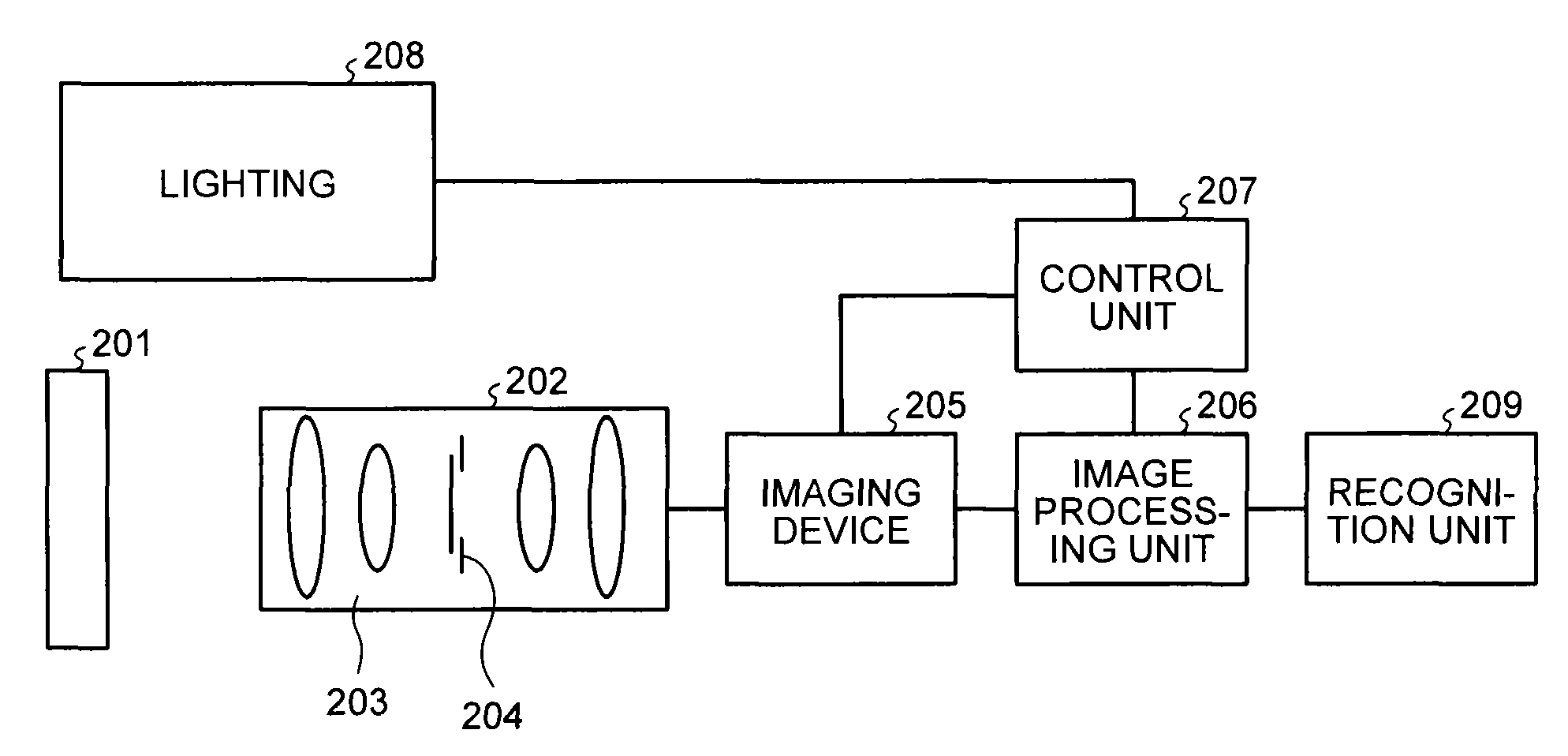
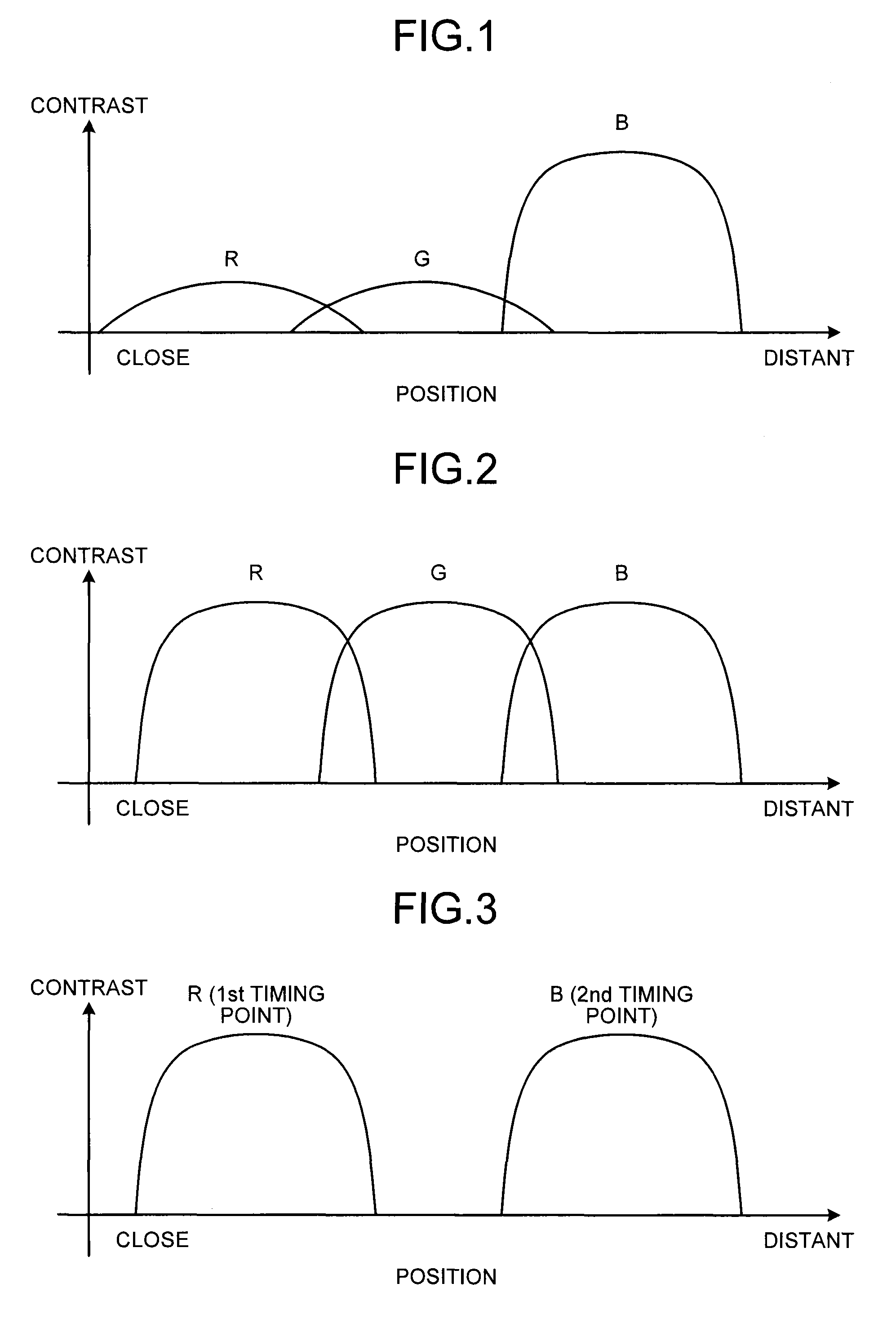
[0019]Relationship between depth of field and contrast is described first. FIGS. 1 to 3 are diagrams each illustrating relationship between imager-to-object distance and contrast at each wavelength.

[0020]To extend depth of field of an imager (imaging system) that utilizes an optical system having different focus positions for different wavelengths of light, it is desirable that such relationship as that illustrated in FIG. 2 holds between contrast and position. However, contrast can vary at different wavelengths (for example, among R (red), G (green), and B (blue) wavelengths) as in image capture using natural light; in that case, a certain wavelength (in the example illustrated in FIG. 1, the R and G wavelengths) can yield low contrast. In this case, even though different wavelengths are used, effective extension of depth of field is not achieved.

[0021]Under the circumstances, the ...


PUM


Abstract

An imaging system includes an optical system, an optical element, a lighting, and an imaging device. The optical system has different focus positions for different wavelengths of light. The optical element extends depth of field of the optical system. The lighting irradiates an object with illumination light of a wavelength that is designated from among multiple wavelengths. The imaging device captures an image of the object that is irradiated with the illumination light and is formed by the optical system.

Description

CROSS-REFERENCE TO RELATED APPLICATIONS[0001]The present application claims priority to and incorporates by reference the entire contents of Japanese Patent Application No. 2014-052791 filed in Japan on Mar. 14, 2014.BACKGROUND OF THE INVENTION[0002]1. Field of the Invention[0003]The present invention relates generally to an imaging system.[0004]2. Description of the Related Art[0005]There is known imagers for reading codes such as barcodes and characters or symbols and including an image sensor such as a charge coupled device (CCD) or a complementary metal-oxide semiconductor (CMOS). One known type of such imagers is an imager that utilizes an optical system having, due to axial chromatic aberrations, different focus positions for different wavelengths of light to provide a large depth of field, thereby providing a large readable range. An example of such an imager is disclosed in Japanese Laid-open Patent Application No. 2011-078097.[0006]However, such conventional imagers are dis...

Claims


Application Information

Patent Timeline
Patent Type & Authority Patents(United States)
IPC IPC(8): G06K7/10G02B27/00G06K7/12
CPCG06K7/10732G02B27/0075G06K7/10544G06K7/10752G06K7/10801G06K7/10811G06K7/12G06K7/10H04N23/60
Inventor MORIHISA, TAIJIROH
Owner RICOH KK
Features
  • R&D
  • Intellectual Property
  • Life Sciences
  • Materials
  • Tech Scout
  • Unparalleled Data Quality
  • Higher Quality Content
  • 60% Fewer Hallucinations
Learn More