
Belt retractor, and method for locking a belt retractor

a belt retractor and belt technology, applied in the field of belt retractors, can solve the problems of complicated support of the belt reel, and achieve the effect of improving the reset of the belt reel and improving the reaction behavior

Active Publication Date: 2016-12-27
TRW AUTOMOTIVE GMBH
View PDF5 Cites 0 Cited by
  • Summary
  • Abstract
  • Description
  • Claims
  • Application Information

AI Technical Summary

Benefits of technology

[0004]It is the object of the invention to provide a belt retractor which allows better reaction behavior mainly with low extension forces as well as an improved reset of the belt reel into the home position.
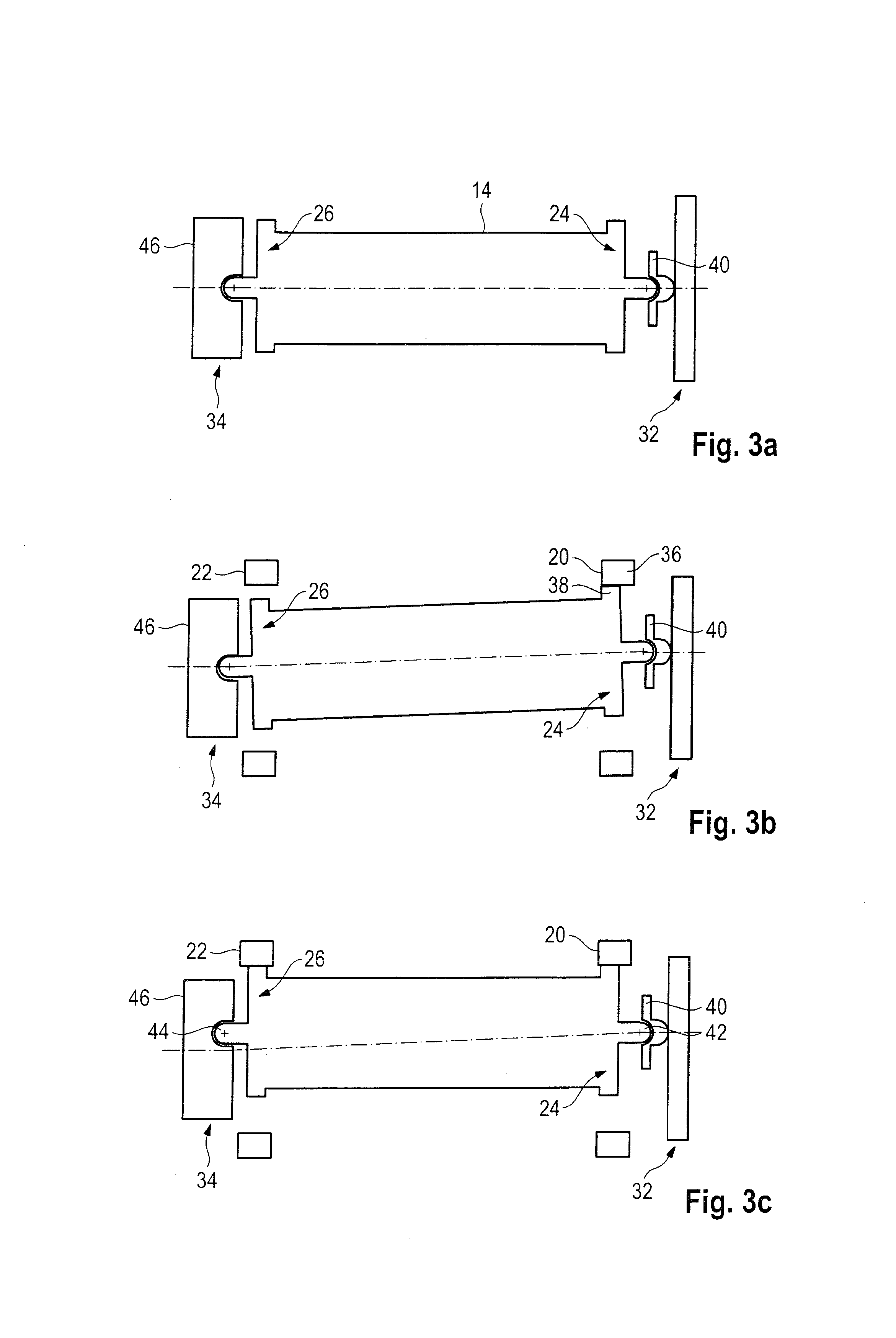
[0008]Preferably a control mechanism is provided which is adapted to displace the belt reel from a home position to a locked position in which the ratchet teeth are engaged with the locking teeth. Such control mechanism ensures that the belt reel and the ratchet teeth of the belt reel, resp., are aligned so that they can engage in the locking teeth of the frame. This control mechanism guarantees that the toothing of the belt reel is introduced in a correct position into the locking teeth of the frame so that engagement of the toothing in the locking teeth is brought about before high loads act on the belt reel.
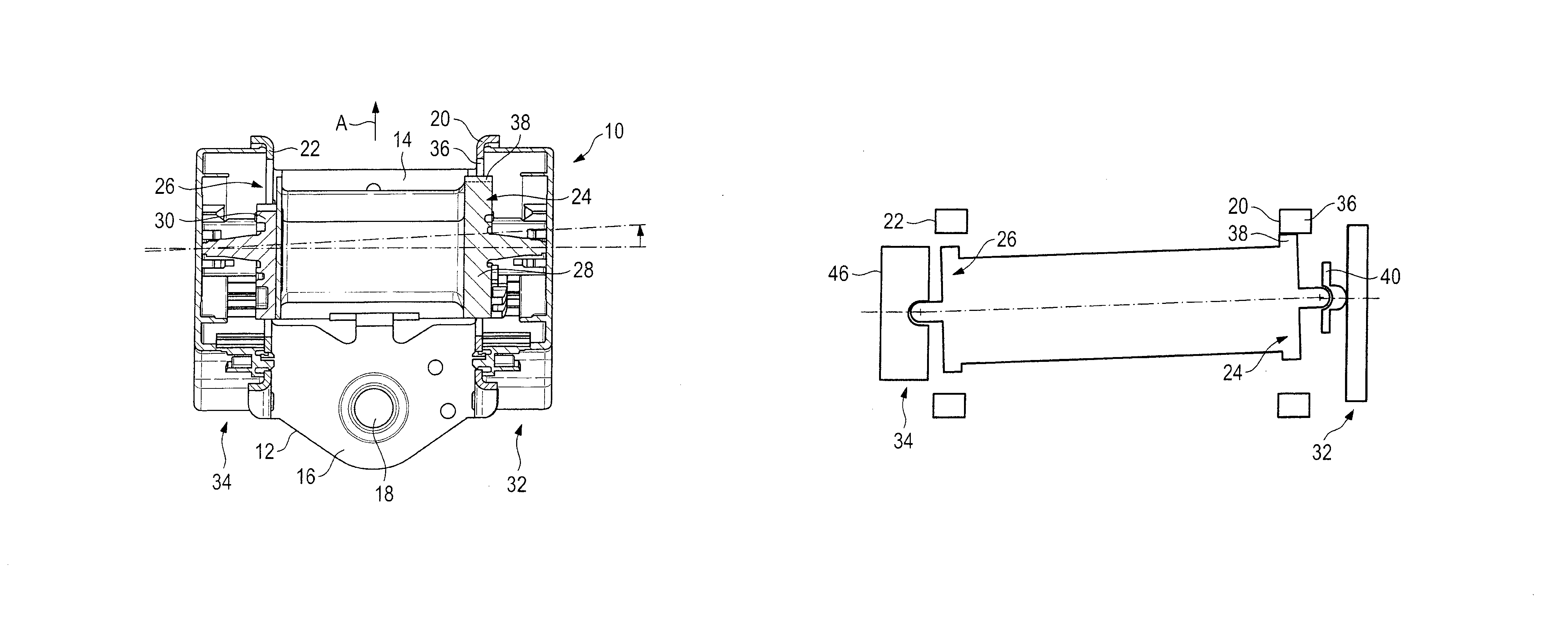
[0011]The locking bearing can have a guiding pin supported in an inclined guiding passage the bottom of which encloses an angle within the range of from 50° to 80°, preferably of 60°, with the longitudinal axis of the belt reel. The guiding passage permits the belt reel to displace out of the home position into the locking position, when appropriate forces act on the belt reel. It is an advantage of this design that no separate components are required to move the belt reel into the locked position and, resp., back into the home position. Since the belt reel is biased in the direction of its axis by such displacement, a reset into the home position takes place automatically. A separate resetting mechanism is thus not required. This guiding passage preferably exhibits a length in the magnitude of 3 mm. It has turned out that already such short distance from the home position to the locking position is sufficient to keep the belt reel in the normal operation, when it is in the home position, reliably supported without the ratchet teeth inadvertently engaging in the locking teeth.
[0013]Preferably each of the locking bearing and / or the load bearing is arranged in a housing shell of the housing and is movable in the same to a limited extent. The housing shell on the one hand permits individual adaptation of the locking bearing and the load bearing, resp., so that the load thresholds of both bearings can be adapted in a rapid and uncomplicated manner. On the other hand, these housing shells safely protect both bearings from external influences so that reliable functioning of the belt retractor is ensured.

Problems solved by technology

Thus a very complicated support of the belt reel is required.

Method used


Image

  • Belt retractor, and method for locking a belt retractor
  • Belt retractor, and method for locking a belt retractor
  • Belt retractor, and method for locking a belt retractor

Examples


Embodiment Construction

[0020]In FIGS. 1 and 2 a belt retractor 10 is illustrated comprising a frame 12 in which a belt reel 14 is rotatably supported. The frame 12 includes a rear member 16 having an opening 18 for fastening the belt retractor 10 as well as two side members 20, 22. Each of them includes an opening 24, 26 within which flanges 28, 30 provided at a respective axial end of the belt reel 14 are accommodated.

[0021]The first side member 20 constitutes a locking, bearing 32 jointly with the first flange 28. In the opening 24 of the first side member 20 locking teeth 36 are provided which interact with ratchet teeth 38 provided on the first flange 28 of the belt reel 14 and in this way can prevent the belt reel 14 from rotating. Hence for locking the belt reel 14 the first flange 28 of the belt reel 14 must be displaced in the extension direction A so that the ratchet teeth 38 engage in the locking teeth 36. Jointly with the second flange 30 the second side member 22 constitutes a load bearing 34....


PUM


Abstract

A belt retractor (10) includes a frame (12) provided with locking teeth (36). A belt reel (14) is rotatably supported in the frame (12) and provided on at least one axial end with ratchet teeth (38) adapted to engage in the locking teeth (36), when the belt reel (14) is shifted from a home position into a locked position. A locking bearing (32) interacts with the belt reel (14) on the side where the ratchet teeth (38) are arranged and keeps the belt reel in the home position up to a first load threshold. A load bearing (34) interacts with the belt reel on the opposite side and keeps the latter in the home position up to a second load threshold. The first load threshold is lower than the second load threshold.

Description

RELATED APPLICATIONS[0001]This application corresponds to PCT / EP2013 / 000651, filed Mar. 6, 2013, which claims the benefit of German Application No. 10 2012 005 330.4, filed Mar. 19, 2012, the subject matter, of which are incorporated herein by reference in their entirety.BACKGROUND OF THE INVENTION[0002]The invention relates to a belt retractor comprising a frame provided with locking teeth and comprising a belt reel which is rotatably supported in the frame and is provided on at least one axial end with ratchet teeth adapted to engage in the locking teeth, when the belt reel is shifted from a home position into a locked position. Further the invention relates to a method for locking a belt reel of such belt retractor.[0003]In said belt retractor the belt reel is displaced relative to the frame for locking so that the ratchet teeth arranged on the belt reel are engaged in the locking teeth provided on the frame. In the previously employed belt retractors the belt reel is displaced i...

Claims


Application Information

Patent Timeline
Patent Type & Authority Patents(United States)
IPC IPC(8): B60R22/38
CPCB60R22/38B60R2022/385
Inventor BEDAK, NIZAMKIELWEIN, THOMASMICHEL, FREDERICRINK, JUERGENSEHIC, DEMAL
Owner TRW AUTOMOTIVE GMBH
Learn More