
Pressure filter and pressing filtering method thereof

A filter press and filter plate technology, applied in the field of filter press solid-liquid separation equipment, can solve the problems of insufficient work efficiency, material leakage, and no connection parts, etc., and achieve low equipment maintenance workload, high work efficiency, and high filtration efficiency. good water effect

Active Publication Date: 2012-12-26
FOSHAN JINKAIDI FILTRATION EQUIP CO LTD
View PDF9 Cites 17 Cited by
  • Summary
  • Abstract
  • Description
  • Claims
  • Application Information

AI Technical Summary

Problems solved by technology

The above-mentioned presses have the following defects: 1. The working efficiency is not high enough, and the water filtration effect is not good enough; 2. The maintenance of the equipment is inconvenient, and the specific performance is as follows: ① If a single spring is damaged, the main board and the sub-board must be completely removed to replace it Spring, the actual operation workload is very large, ② There is no connecting piece between the sub-frame and the main board, when the sub-board is disassembled in some cases, the sub-frame will fall without support; There is a spring between them, and the elastic force of the spring will also bounce off the sub-frame; 3. There is a hidden danger of material leakage during the pressing process, which is specifically manifested in the fact that the contact surface between the sub-frame and the sub-plate will move, and the material will come into contact with the two. Leakage in the gap caused by surface movement; at the same time, during the operation of the filter press, it is difficult to maintain the alignment of the main board and the sub-board, and if there is a deviation, it will also cause material leakage

Method used


Image

  • Pressure filter and pressing filtering method thereof
  • Pressure filter and pressing filtering method thereof
  • Pressure filter and pressing filtering method thereof

Examples


Embodiment Construction

[0039] The technical solutions of the present invention will be further described below in conjunction with the accompanying drawings and through specific implementation methods.

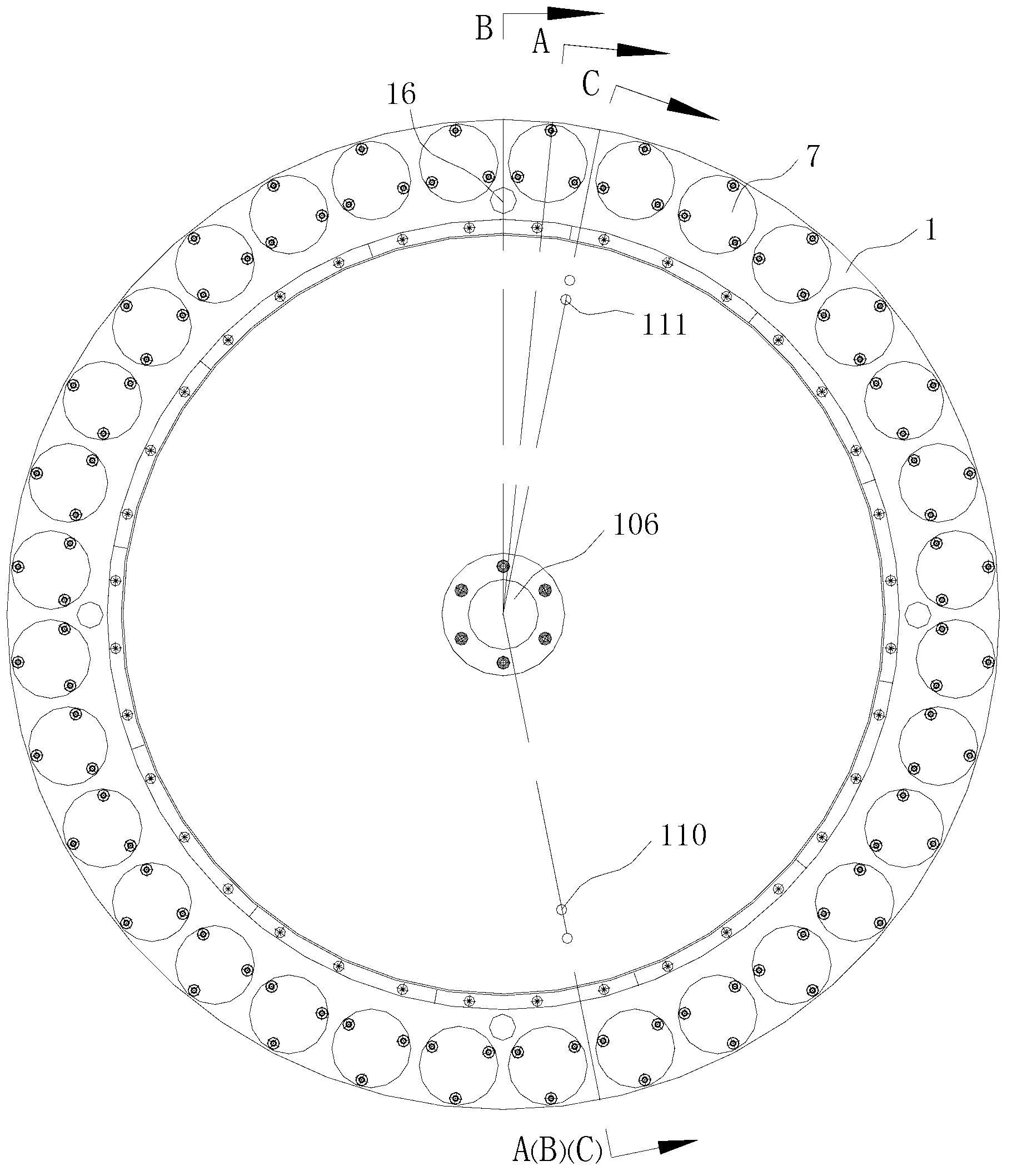
[0040] A filter press, including several filter plate groups connected in sequence, each filter plate group includes a main board, a sub The plate and the sub-frame are located on the same side of the main board; the other side of the main board is set in contact with the sub-frame of the adjacent filter plate group, and there is a volume-variable space between the adjacent filter plate groups to accommodate the material to be filtered. In the filter press space, each filter plate group has a material channel, and the material channel is connected with the filter press space, and the material enters the filter press space through the material channel. In each filter plate group, the opposite side of the sub-plate and the main plate A filter screen is set, and the outside of the filter screen is cove...


PUM


Abstract

The invention discloses a pressure filter comprising a plurality of filtering plate sets which are connected in sequence, wherein each filtering plate set comprises a main plate, an auxiliary plate, and an auxiliary frame, the auxiliary plate is fixed on one side of the main plate and on the same side of the main plate, the auxiliary frame is sleeved on the periphery of the auxiliary plate in a sliding mode, and the other side of the main plate is connected with the auxiliary frame of the adjacent filtering plate sets. Moreover, volume-changeable pressing filtering space used for containing materials is arranged between the adjacent filtering plate sets. Each filtering plate set is provided with a material channel which is communicated with the pressing filtering space. The other side of the main plate, opposite to the contact face of the auxiliary plate, is provided with a filtering mesh. Filter cloth wraps outside the filtering mesh. Each filtering plate set is also provided with a gas channel and a liquid channel which are communicated with the outside to the pressing filtering space. The pressure filter is high in structure reliability, has no leakage of the materials, and is convenient to maintain. The invention further provides a pressing filtering method. As pressing filtering and drying above the third level are adopted, water-filtering effect is better, size of the pressed and filtered material is larger, water containing rate of the materials is lower, work efficiency is higher, and production is higher.

Description

technical field [0001] The invention relates to the technical field of filter press solid-liquid separation equipment, in particular to a filter press and a filter press method thereof. Background technique [0002] Filter press is a kind of equipment that separates materials from solid and liquid through pressure filtration. It is widely used in food, chemical, environmental protection and sewage treatment industries, especially for the separation of sticky and fine matter. It has unique advantages. For example, the sludge produced by chemical and domestic sewage treatment has a high water content and must be dehydrated to reduce its volume before it can be discharged. The cost of landfilling sludge is very high, which may reach 1,000 yuan per ton. After dehydration treatment, the volume will be reduced by more than 50%, and the energy consumption will be reduced, which can significantly reduce the cost of sludge treatment in enterprises and reduce landfill sites . [000...

Claims


Application Information

Patent Timeline
Patent Type & Authority Applications(China)
IPC IPC(8): B01D25/12B01D37/00B01D37/04
Inventor 庞仲达
Owner FOSHAN JINKAIDI FILTRATION EQUIP CO LTD
Learn More