Astigmatic depth from defocus imaging using intermediate images and a merit function map

a technology of merit function and depth, applied in the field of depth from defocus optical apparatus, can solve the problems of insufficient depth accuracy, infrequent depth data, and high cost of certain applications

Active Publication Date: 2016-12-27
ELLIS AMALGAMATED
View PDF19 Cites 0 Cited by
  • Summary
  • Abstract
  • Description
  • Claims
  • Application Information

AI Technical Summary

Problems solved by technology

For example, time-of-flight, structured illumination, or existing depth-from-defocus devices, are typically undesirably sensitive to ambient light and object color or reflectivity, provide infrequent depth data, are too expensive for certain applications, or have insufficient depth accuracy.

Method used


Image

  • Astigmatic depth from defocus imaging using intermediate images and a merit function map
  • Astigmatic depth from defocus imaging using intermediate images and a merit function map
  • Astigmatic depth from defocus imaging using intermediate images and a merit function map

Examples


Embodiment Construction

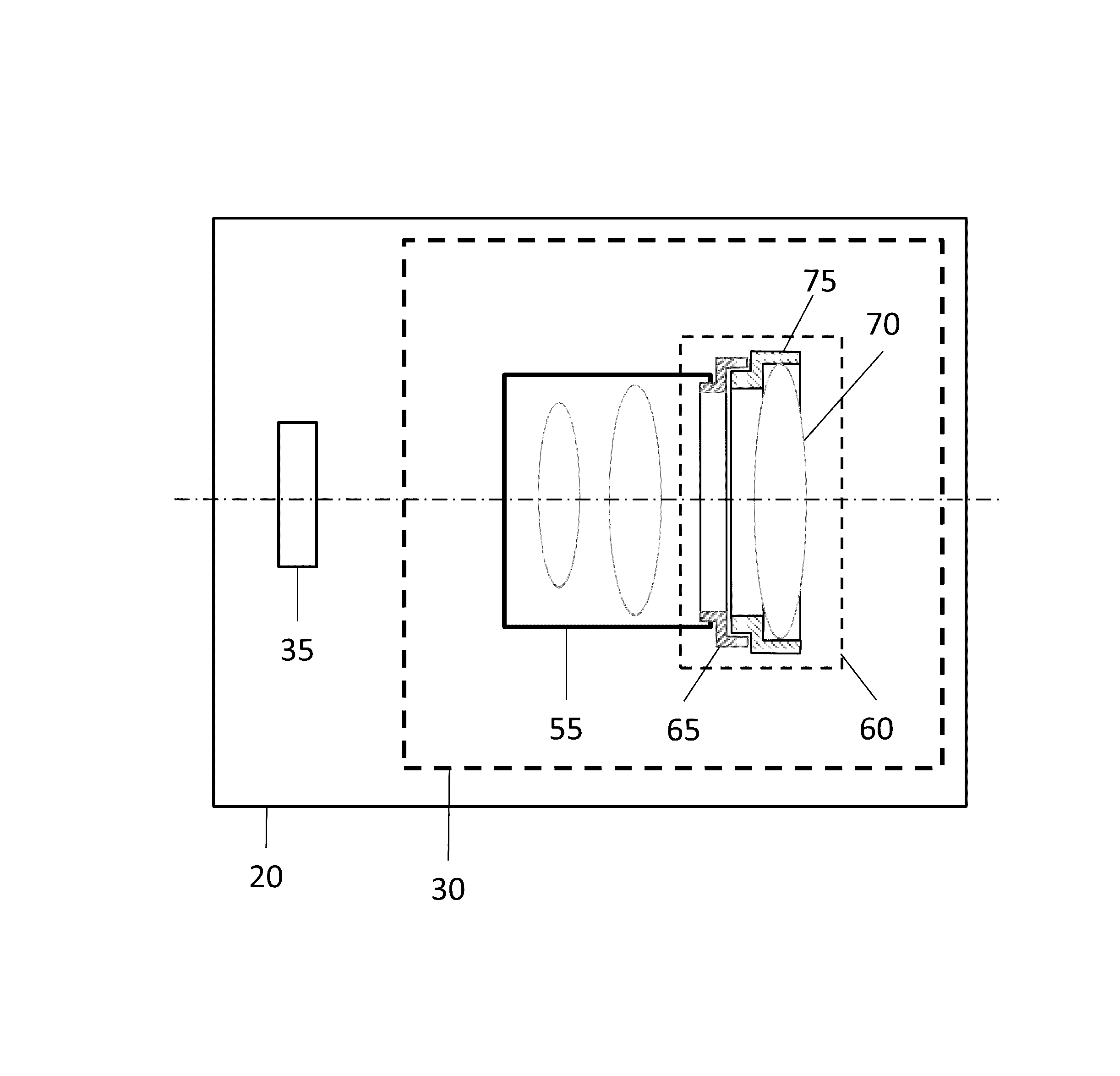
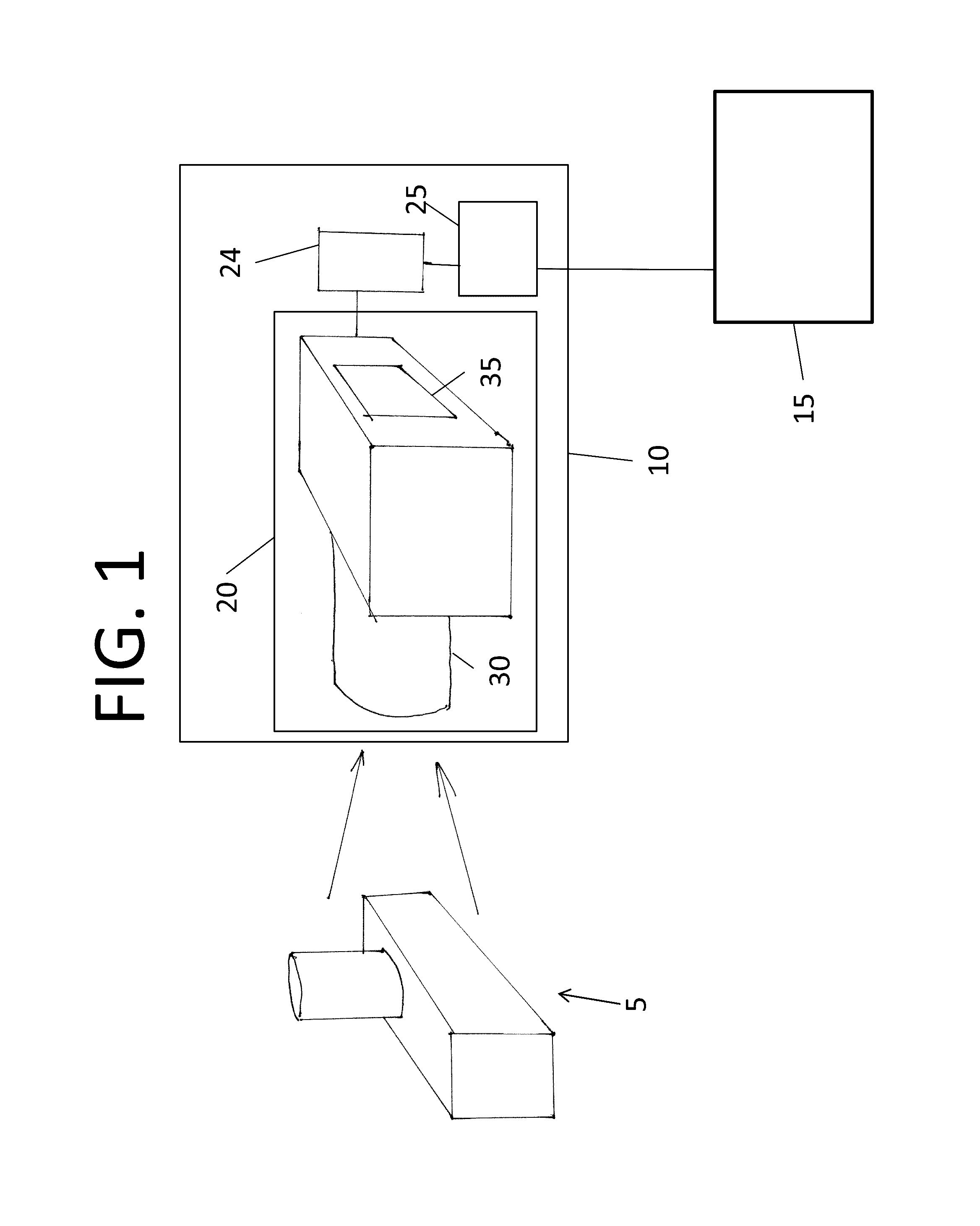
[0041]Referring to FIG. 1, in a typical embodiment of the astigmatic rangefinder, a rangefinder 10 images a scene 5 to produce at least one depth map 15. The rangefinder 10 has a depth camera 20 and a processing system 25. The depth camera 20 has imaging optics 30 and a sensor 35.

[0042]The depth camera 20 produces image data 24 (alternatively, an “input image”) that is made available to the processing system 25.

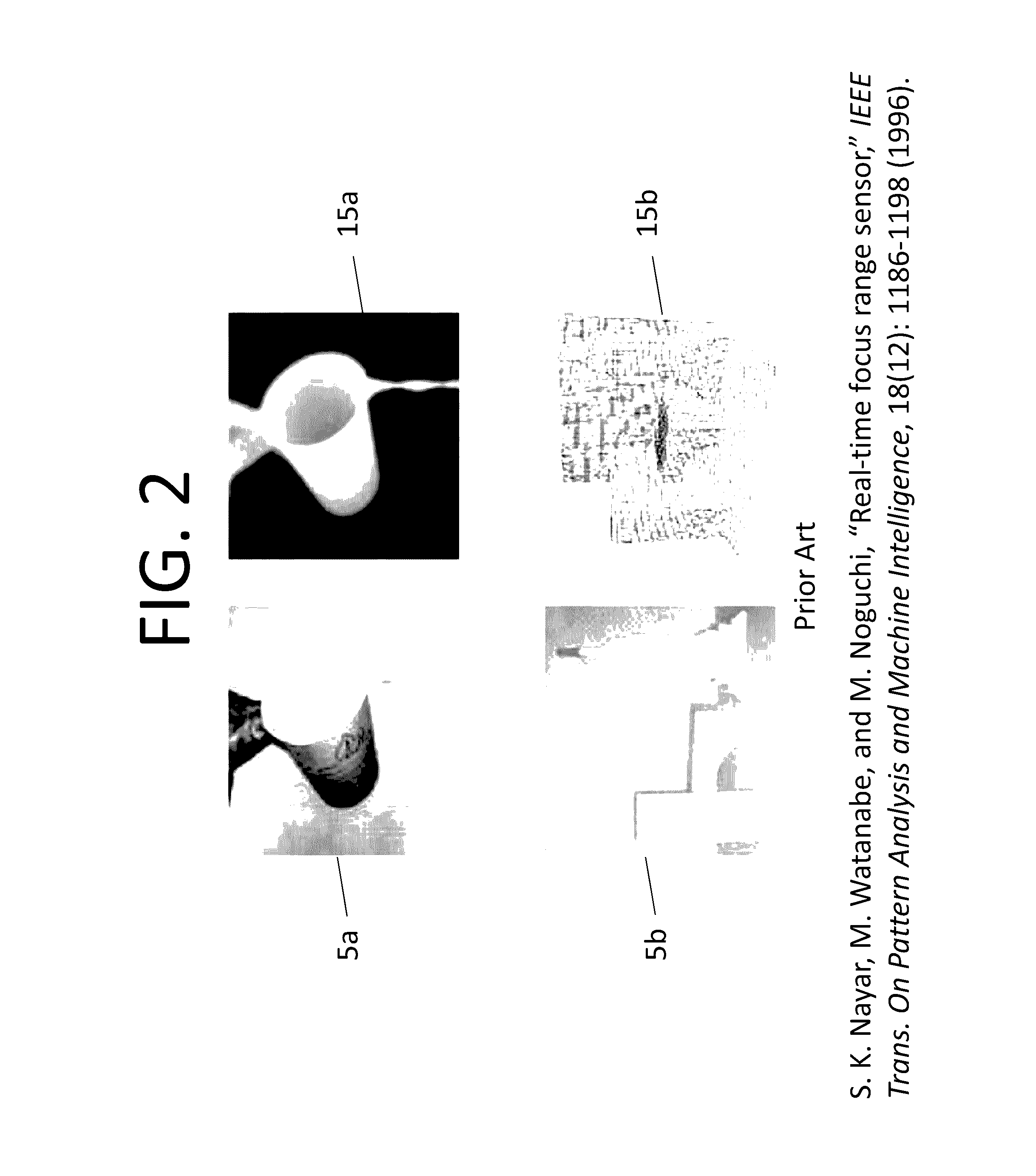
[0043]FIG. 2 illustrates scenes and depth maps as generated by an existing rangefinder. The top row shows an example of a scene 5a of liquid being poured out of a container and the corresponding depth map 15a. Usually, a depth maps is a two-dimensional scalar array in which each scalar corresponds to a distance. For example, a value near 0 indicates “near” and a value near 255 indicates “far.” It is convenient to depict depth maps graphically, as shown by the exemplary depth map 15a. In this case, “near” is rendered in white, intermediate distances are rendered in gray, and “...


PUM


Abstract

A rangefinder has a depth camera and a computer. The depth camera is positioned to receive electromagnetic energy from a scene. Imaging optics and a sensor in the camera generate an input image based on electromagnetic energy. The computer receives the input image, calculates intermediate images by applying differentiation operators along different axes to the input image, creates a merit function map, and computes a depth map from the merit function map.

Description

CROSS-REFERENCE TO RELATED APPLICATIONS[0001]This application claims the benefit of the Apr. 18, 2013 priority date of U.S. Provisional Application 61 / 854,149, the contents of which are herein incorporated by reference.FIELD OF INVENTION[0002]The present invention relates to three-dimensional imaging systems, and particularly to depth-from-defocus optical apparatus.BACKGROUND OF THE INVENTION[0003]Various optical systems have been developed for estimating the distance to and shape of objects. These are sometimes referred to as rangefinders, range sensors, and depth map cameras. Here, they will be referred to as “rangefinders.” A rangefinder estimates distances to one or more regions within a scene. The scene can contain one or more objects.[0004]Some rangefinders estimate depth by analyzing the blur that is present in at least one image of the scene. Examples of such rangefinders are described in S. K. Nayar, M. Watanabe, and M. Noguchi, “Real-Time Focus Range Sensor,” IEEE Transact...

Claims


Application Information

Patent Timeline
Patent Type & Authority Patents(United States)
IPC IPC(8): H04N13/02G06T5/00
CPCG06T5/003H04N13/0253H04N13/0271G06T2200/04G06T2207/10028H04N13/271H04N13/254
Inventor TSUKANOV, VITALY G.BASHTYK, YURIY V.FAVALORA, GREGG E.
Owner ELLIS AMALGAMATED
Why Eureka
Try Eureka