Optical fiber drawing method and optical fiber drawing apparatus

a drawing method and optical fiber technology, applied in the field of optical fiber drawing methods and optical fiber drawing apparatuses, can solve the problems of reducing the capacity of drawing furnace space, reducing the height of an upper chamber, and reducing the variation of the pressure in the furna

Active Publication Date: 2017-02-14
SUMITOMO ELECTRIC IND LTD
View PDF12 Cites 0 Cited by
  • Summary
  • Abstract
  • Description
  • Claims
  • Application Information

AI Technical Summary

Benefits of technology

[0024]According to the invention, the height of an upper chamber is decreased and the sleeve member is inserted into space in the furnace and thereby, capacity of space in the drawing furnace can be decreased and variations in pressure in the furnace can be reduced. Also, the first seal part with which the outer peripheral surface of the glass preform is sealed and the second seal part with which the sleeve member is sealed can use the seal mechanism of the same form, and a stable seal can be achieved.

Problems solved by technology

Also, normally, a diameter of the upper end of the glass preform is decreased in a taper shape and a dummy rod (also called a support rod) with a small diameter is connected and the glass preform is hung and supported inside the furnace core tube of the drawing furnace, but it is difficult to seal a joining portion of the dummy rod and the tapered portion with the diameter changing greatly, and it is difficult to fill the inside of the drawing furnace with the inert gas etc.
However, in this method, as drawing of the glass preform progresses and the glass preform is downwardly moved, capacity of space in the upper chamber is increased, with the result that pressure in the furnace varies and the flow of gas such as the inert gas fed to the inside of the furnace core tube changes with time and thereby, the amount of heat transfer of a melt part of the glass preform changes and the diameter of the glass fiber during the drawing varies.

Method used


Image

  • Optical fiber drawing method and optical fiber drawing apparatus
  • Optical fiber drawing method and optical fiber drawing apparatus
  • Optical fiber drawing method and optical fiber drawing apparatus

Examples


Embodiment Construction

[0030]A concrete example of an optical fiber drawing method and an optical fiber drawing apparatus according to an embodiment of the invention will hereinafter be described with reference to the drawings.

[0031]In addition, a resistance furnace for heating a furnace core tube by a heater will be described below by way of example, but the invention can also be applied to an induction furnace for applying a high-frequency power source to a coil and inductively heating a furnace core tube.

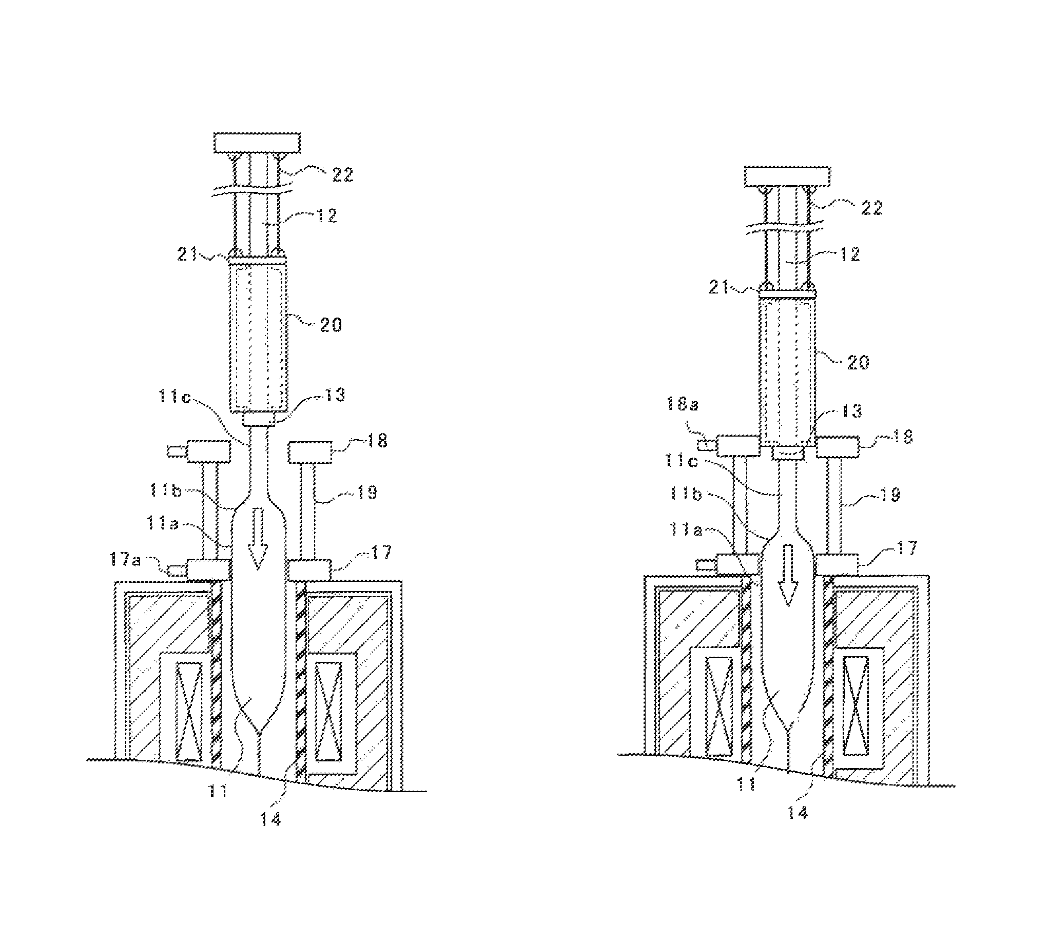
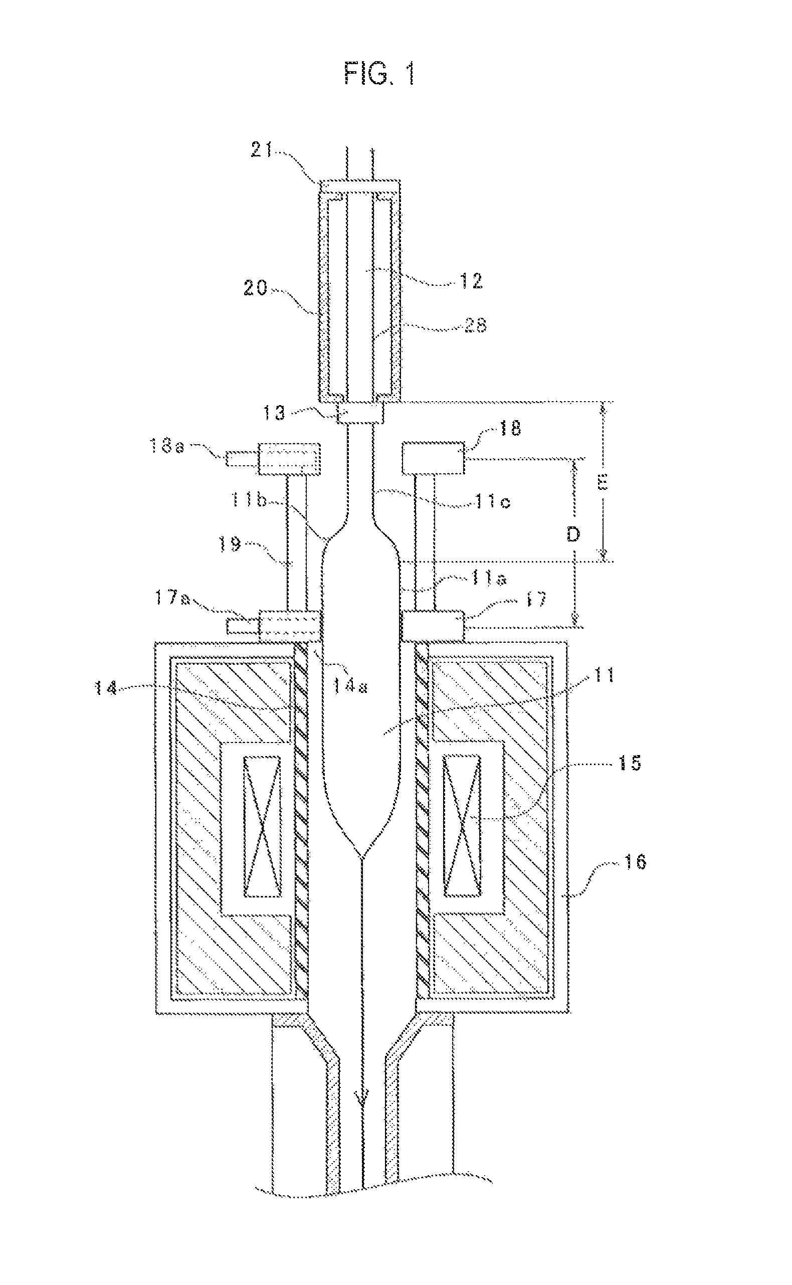
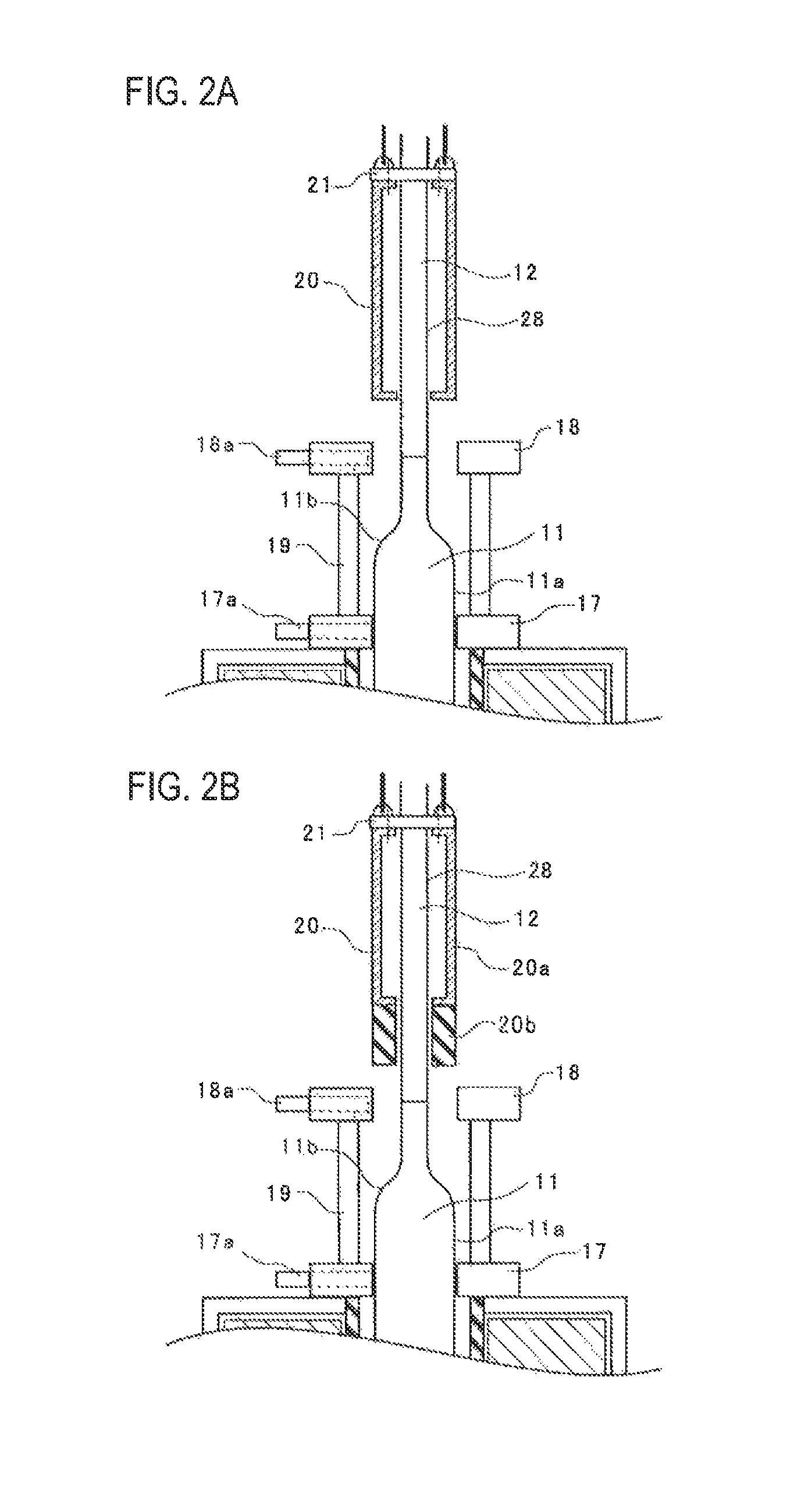
[0032]In FIGS. 1 to 4, numeral 11 shows a glass preform, and numeral 11a shows a straight trunk part, and numeral 11b shows a taper part, and numeral 11c shows a diameter contracted part, and numeral 12 shows a dummy rod, and numeral 13 shows a joining member, and numeral 14 shows a furnace core tube, and numeral 15 shows a heater, and numeral 16 shows a furnace cabinet, and numeral 17 shows a first seal part, and numeral 17a shows a gas supply port, and numeral 18 shows a second seal part, and numeral...


PUM

PropertyMeasurementUnit
temperatureaaaaaaaaaa
diameteraaaaaaaaaa
diameteraaaaaaaaaa

Abstract

Capacity of space in a drawing furnace is decreased so as to reduce variations in pressure in the furnace and also the side of an insertion port of a glass perform is stably sealed. When drawing is started, an outer peripheral surface of the optical fiber glass preform 11 is sealed with a first seal part 17 of the seal mechanism. After a vicinity of a taper part of the optical fiber glass preform 11 starts to pass through the first seal part 17, switching to a second seal part 18 arranged above the first seal part 17 is performed, and an outer peripheral surface of a sleeve member 20 fixed so as to surround an outer periphery of the dummy rod 12 is sealed with the second seal part 18.

Description

[0001]This application is a 371 of PCT / JP2014 / 053806 filed 18 Feb. 2014TECHNICAL FIELD[0002]The present invention relates to an optical fiber drawing method and apparatus for drawing an optical fiber by heating and melting an optical fiber glass preform.BACKGROUND ART[0003]An optical fiber glass preform (hereinafter called a glass preform) is heated and melted by a heater etc. to thereby draw an optical fiber through a drawing furnace. Since the temperature of the inside of the drawing furnace becomes very high (2000° C. or higher), carbon is normally used in, for example, a furnace core tube for surrounding the glass preform. This carbon is oxidized and consumed in a high-temperature oxygen-containing atmosphere. In order to prevent this state, nitrogen gas or rare gas such as argon gas or helium gas (hereinafter called an inert gas etc.) is fed to the inside of the drawing furnace.[0004]Also, normally, a diameter of the upper end of the glass preform is decreased in a taper shape ...

Claims


Application Information

Patent Timeline
Patent Type & Authority Patents(United States)
IPC IPC(8): C03B37/027C03B37/029
CPCC03B37/02736C03B37/029C03B2205/80C03B2205/92
Inventor OKAZAKI, IWAOYAMAZAKI, TAKASHIKONISHI, TATSUYATSUNEISHI, KATSUYUKI
Owner SUMITOMO ELECTRIC IND LTD
Why Eureka
Try Eureka