Middle ear implantable microphone

a microphone and implantable technology, applied in electrotherapy, artificial respiration, therapy, etc., can solve the problems of large electrostatic force, low frequency very limited, low frequency below 200 hz, etc., to minimize static deflection of the transducer, low signal dynamic, and maximum resonance frequency

Active Publication Date: 2017-02-28
MED EL ELEKTROMEDIZINISCHE GERAETE GMBH
View PDF17 Cites 0 Cited by
  • Summary
  • Abstract
  • Description
  • Claims
  • Application Information

AI Technical Summary

Problems solved by technology

Hence low frequencies below 200 Hz cannot be measured well.
It also suffers from a large electrostatic force introduced by the electrets.
Due to the high resonance frequency, the microphone of Young et al., is very limited in the low frequency range
Due to the high resonance frequency, measurements are possible in the range of 900 Hz to 10 kHz, but are too limited in lower frequencies

Method used


Image

  • Middle ear implantable microphone
  • Middle ear implantable microphone
  • Middle ear implantable microphone

Examples


Embodiment Construction

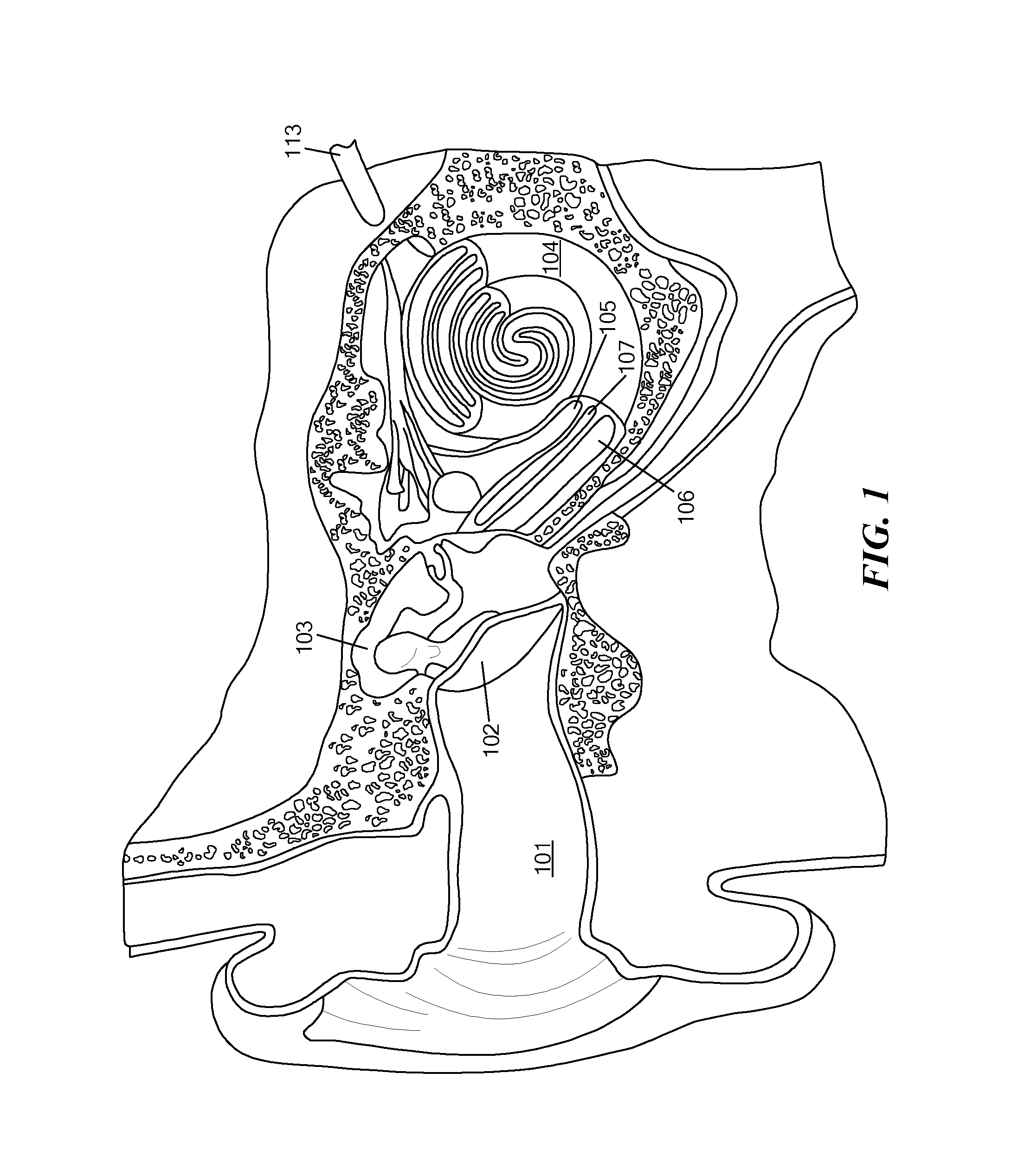
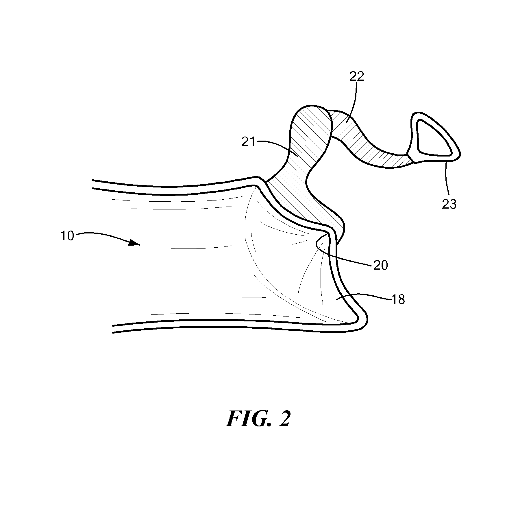
[0033]In illustrative embodiments, a middle ear implantable microphone acting as a seismic sensor with high pass filter characteristics (as opposed to an accelerometer), and having a resonance frequency within a predetermined operating frequency range of, without limitation, between 100 Hz and 10 kHz, is described. Selecting such a resonance frequency enables the microphone device to have some favourable parameters, such as a very low mass of the vibration detecting unit. Possible disadvantages of a non-flat frequency characteristic in the operating range of the microphone are compensated by the entire micro system environment comprising both the anatomical and functional structure of the ear from tympanic membrane to the brain and the implantable microphone itself. Details are described below.

[0034]For the design of an implantable middle ear microphone, the following three boundary conditions become important.

[0035]1. The Ossicle Chain Deflection Over Frequency and the Physiology o...


PUM


Abstract

A method of sensing vibrations in the middle ear is presented. The method includes implanting a transducer in the middle ear. The transducer measures vibration, within a predetermined frequency range, of at least one component of the middle ear. The transducer has a resonance frequency within the predetermined frequency range, and further has a limited frequency response in a portion of the frequency range. The implanting includes operatively coupling the implant to the at least one component of the middle ear such that the limited frequency response of the transducer is complimentary to, and compensated by, the frequency characteristics of the at least one component of the middle ear.

Description

CROSS-REFERENCE TO RELATED APPLICATIONS[0001]This application is a continuation of Patent Cooperation Treaty Application PCT / US2011 / 050280, filed Sep. 2, 2011, which in turn claims priority from U.S. provisional application Ser. No. 61 / 379,833, entitled “Middle Ear Implantable Microphone,” filed Sep. 3, 2010, each of which are hereby incorporated herein by reference in its entirety.TECHNICAL FIELD[0002]The present invention relates to an implantable microphone sensor useable with a cochlear implant or hearing aid, and more particularly to an implantable microphone that coupled to a structure within the middle ear.BACKGROUND ART[0003]FIG. 1 shows the anatomy of a normal human ear. A normal ear transmits sounds through the outer ear 101 to the tympani membrane (i.e., the eardrum) 102, which moves the bones of the middle ear 103, which in turn excites the cochlea 104. The cochlea (or inner ear) 104 includes an upper channel known as the scala vestibuli 105 and a lower channel known as ...

Claims


Application Information

Patent Timeline
Patent Type & Authority Patents(United States)
IPC IPC(8): H04R25/00H04R19/04H04R31/00A61N1/36H04R3/06
CPCH04R25/50H04R19/04H04R25/604H04R31/00A61N1/36032H04R3/06H04R25/606H04R2201/003H04R2225/67H04R2410/03H04R2430/03
Inventor KOHL, FRANZHORTSCHITZ, WILFRIEDSACHSE, MATTHIASSAUTER, THILO
Owner MED EL ELEKTROMEDIZINISCHE GERAETE GMBH
Why Eureka
Try Eureka