Image forming apparatus and process cartridge

a technology of image forming apparatus and process cartridge, which is applied in the direction of electrographic process apparatus, instruments, developers, etc., can solve the problems of filming phenomenon likely to deteriorate developability, stick-slip motion, and defective cleaning

Active Publication Date: 2017-03-07
RICOH KK
View PDF16 Cites 2 Cited by
  • Summary
  • Abstract
  • Description
  • Claims
  • Application Information

AI Technical Summary

Benefits of technology

[0032]In accordance with some embodiments of the present invention, an image forming apparatus which prevents the occurrence of stick-slip motion of the cleaning blade to suppress defective cleaning of the image bearer and formation of adhered matter on the image bearer is provided.
[0033]In accordance with some embodiments of the present invention, an image forming apparatus which has a good combination of offset resistance and filming resistance and is capable of providing high-definition high-quality image for an extended period of time is provided.

Problems solved by technology

When the elastic body blade, which may be made of polyurethane rubber, is brought into contact with the image bearer to clean the image bearer, the tip of the blade is pulled in the direction of movement of the image bearer due to the frictional force generated between the image bearer and the cleaning blade, thereby causing stick-slip motion.
If the image bearer is cleaned during the occurrence of stick-slip motion, toner particles will pass through between the elastic body blade and the image bearer, resulting in defective cleaning.
The filming phenomenon is likely to deteriorate developability.
It is generally very difficult to contain the wax in the form of fine particles inside the toner without exposing them at the surface of the toner because the wax particles are inevitably finer than the toner particles.
If the release agent in the form of a large block is achieved by excessively increasing the content of the release agent, the toner will deteriorate in strength and become easy to get crushed, deteriorating resistance to the filming phenomena.

Method used


Image

  • Image forming apparatus and process cartridge
  • Image forming apparatus and process cartridge
  • Image forming apparatus and process cartridge

Examples


examples

Preparation of Toner 1

Preparation of Colorant Dispersion Liquid

[0284]A carbon black dispersion liquid was prepared as follows.

[0285]First, 20 parts of a carbon black (REGAL 400 from Cabot Corporation) and 2 parts of a colorant dispersant (AJISPER PB821 from Ajinomoto Fine-Techno Co., Inc.) were primarily dispersed in 78 parts of ethyl acetate using a mixer having stirrer blades. The resulting primary dispersion liquid was subjected to a dispersion treatment using a DYNOMILL to more finely disperse the carbon black and completely remove aggregations by application of a strong shearing force. The resulting secondary dispersion liquid was filtered with a polytetrafluoroethylene (PTFE) filter (Fluoropore™ Membrane Filter FHLP09050 available from Nihon Millipore K.K.) having a pore size of 0.45 μm to further disperse the carbon black to submicron order. Thus, a carbon black dispersion liquid was prepared.

Preparation of Toner Composition Liquid

[0286]First, 20 parts of a wax 1, serving as ...


PUM


Abstract

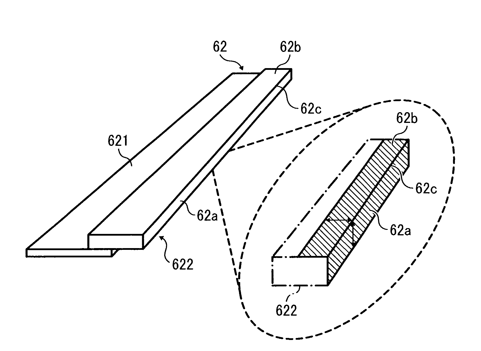
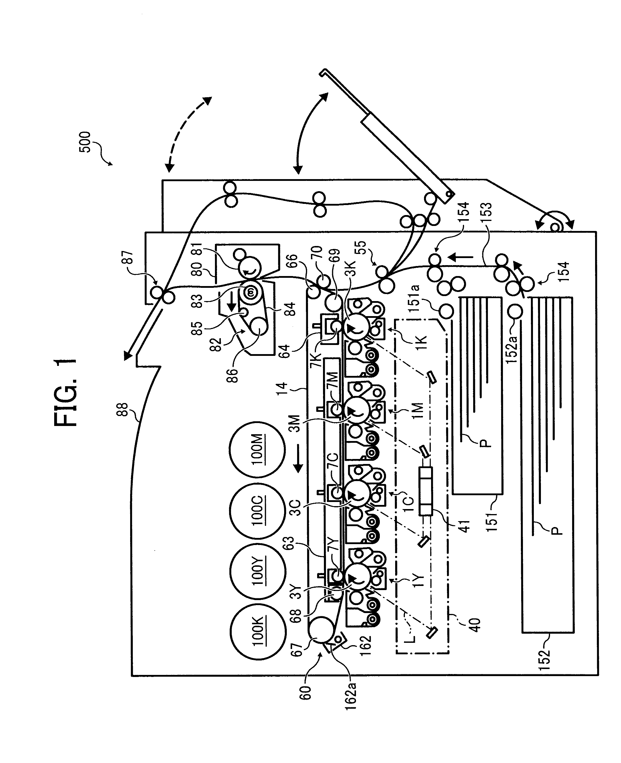
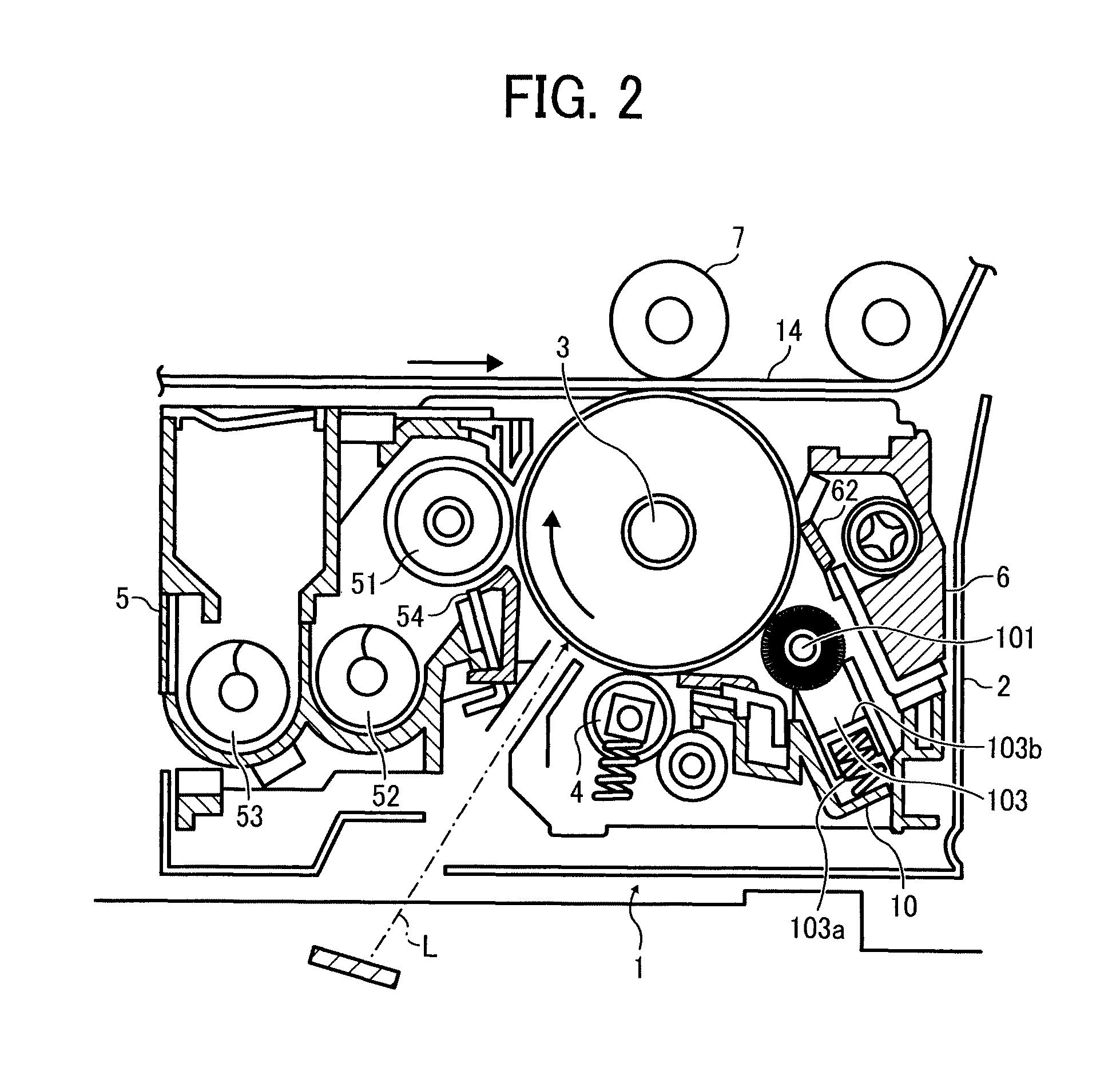
An image forming apparatus is provided which includes an image bearer, a charger to charge the image bearer, a latent image forming device to form an electrostatic latent image on the image bearer, a developing device to develop the electrostatic latent image with a toner, a transfer device to transfer the toner image onto a transfer medium, and a cleaning blade to remove residual toner particles remaining on the image bearer. The toner includes a binder resin and a release agent. The release agent has a longest length Lmax in the toner, which is equal to or greater than 1.1 times a maximum Feret diameter Df of the toner. The cleaning blade includes a strip-like elastic body blade having a contact part with the image bearer. The contact part includes a cured product of an ultraviolet curable composition including an acrylate or methacrylate compound having an alicyclic structure.

Description

CROSS-REFERENCE TO RELATED APPLICATIONS[0001]This patent application is based on and claims priority pursuant to 35 U.S.C. §119(a) to Japanese Patent Application Nos. 2015-056443 and 2015-078349, filed on Mar. 19, 2015 and Apr. 7, 2015, respectively, in the Japan Patent Office, the entire disclosure of each of which is hereby incorporated by reference herein.BACKGROUND[0002]Technical Field[0003]The present disclosure relates to an image forming apparatus and a process cartridge.[0004]Description of the Related Art[0005]In a typical electrophotographic image forming apparatus, residual toner particles remaining on a photoconductor or image bearer without being transferred onto a transfer sheet or intermediate transfer medium are removed by a cleaner. The cleaner generally contains a cleaning blade having a strip-like shape for its simple configuration and excellent cleaning ability. Such a cleaning blade is typically composed of an elastic body blade having a strip-like shape which m...

Claims


Application Information

Patent Timeline
Patent Type & Authority Patents(United States)
IPC IPC(8): G03G21/00G03G9/00
CPCG03G21/0017G03G9/00G03G15/0225G03G15/161G03G9/0819G03G9/08782
Inventor GOHDA, SHOHEIGONDOH, MASANOBUTOYAMA, KAORISAKON, YOHTAOHMORI, MASAHIROAOYAMA, YUKANAKAMURA, YUTAMORIYA, YOSHIHIROKOJIMA, SATOSHI
Owner RICOH KK
Why Eureka
Try Eureka