
Image forming apparatus

a technology of image forming apparatus and charging member, which is applied in the direction of electrographic process apparatus, instruments, optics, etc., can solve the problems of unfavorable image deterioration, faulty cleaning in the next image, and inability to maintain satisfactory cleaning performance, etc., to suppress faulty cleaning and suppress deterioration of current carrying capacity of charging member

Active Publication Date: 2017-03-28
CANON KK
View PDF5 Cites 0 Cited by
  • Summary
  • Abstract
  • Description
  • Claims
  • Application Information

AI Technical Summary

Benefits of technology

The solution effectively suppresses deterioration of the current carrying capacity and prevents faulty cleaning and negative ghost, extending the device's lifetime and ensuring high-quality image formation.

Problems solved by technology

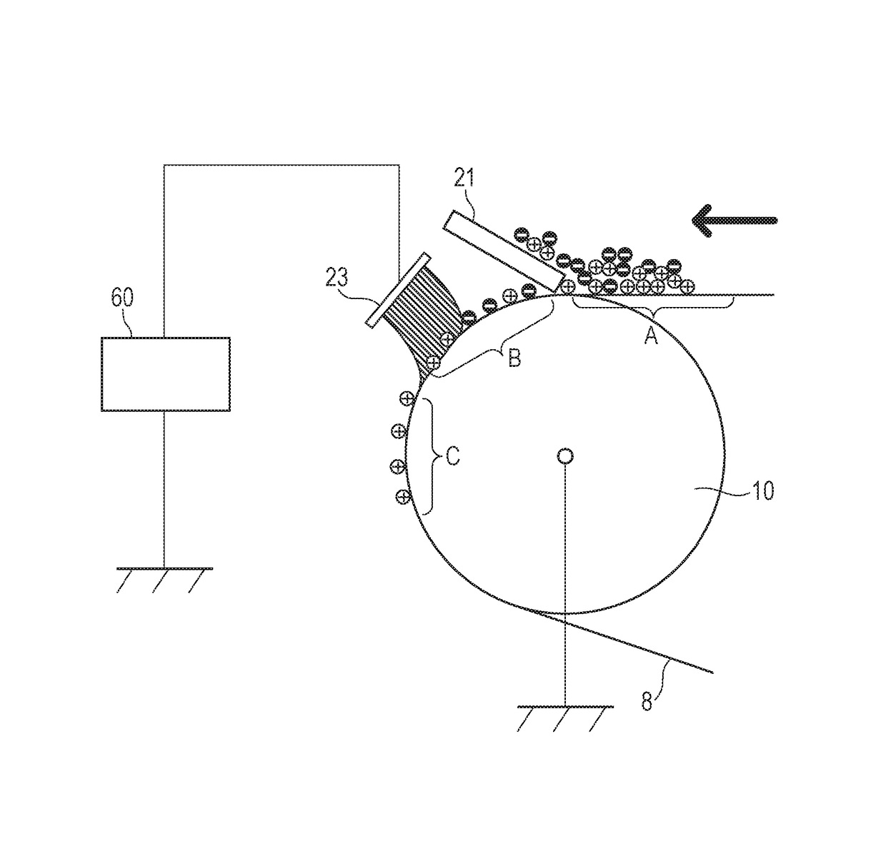
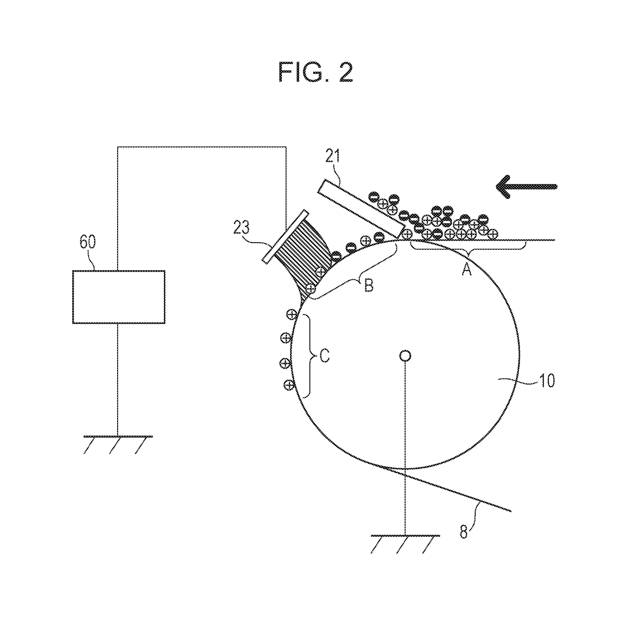
While a low-cost and satisfactory cleaning performance can be expected from the cleaning method, the method is susceptible to unevenness of the surface of the intermediate transfer body, and there are cases in which a satisfactory cleaning performance cannot be maintained owing to the residual secondary transfer toner passing through the cleaning blade around the uneven portion.
When the absolute value of the triboelectricity (the charge amount per unit weight of the toner) of the toner is lower than a desired value when the toner is being collected by the photosensitive member, there are cases in which faulty cleaning occurs in the next image that is being formed when continuous image formation is performed.
Accordingly, toner with a weak positive polarity (in other words, toner with a small absolute value) or toner with a triboelectricity having a negative polarity is not collected by the photosensitive member at the primary transfer portion and the toner that has not been collected by the photosensitive member unfavorably remains in the image that is in formation.
Accordingly, there are cases in which the residual secondary transfer toner of the previous image creates an image defect in the image that is in formation.
Furthermore, the absorbed toner of the next image unfavorably returns to the photosensitive member without being primarily transferred to the intermediate transfer body.
As a result, since the toner at a portion corresponding to the previous image is unfavorably returned to the photosensitive member, a difference in density is created in the image that is being formed.
As described above, with the collection at transfer method, if the charging current distributed to the charging device is large, the negative ghost worsens and when small, faulty cleaning, on the other hand, worsens; accordingly a charging current that prevents both need to be set.
However, it has been found that in the hybrid cleaning method described above, when the lifetime of the device is increased, a new problem described below is met.
As a result, due to deterioration in the current carrying capacity of the charging device, an increase in resistance occurs making it difficult for the charging current needed to charge the passed-though toner of flow; accordingly, there are cases in which faulty cleaning occur.

Method used


Image

  • Image forming apparatus
  • Image forming apparatus
  • Image forming apparatus

Examples


first exemplary embodiment

(1) Overall Configuration of Image Forming Apparatus

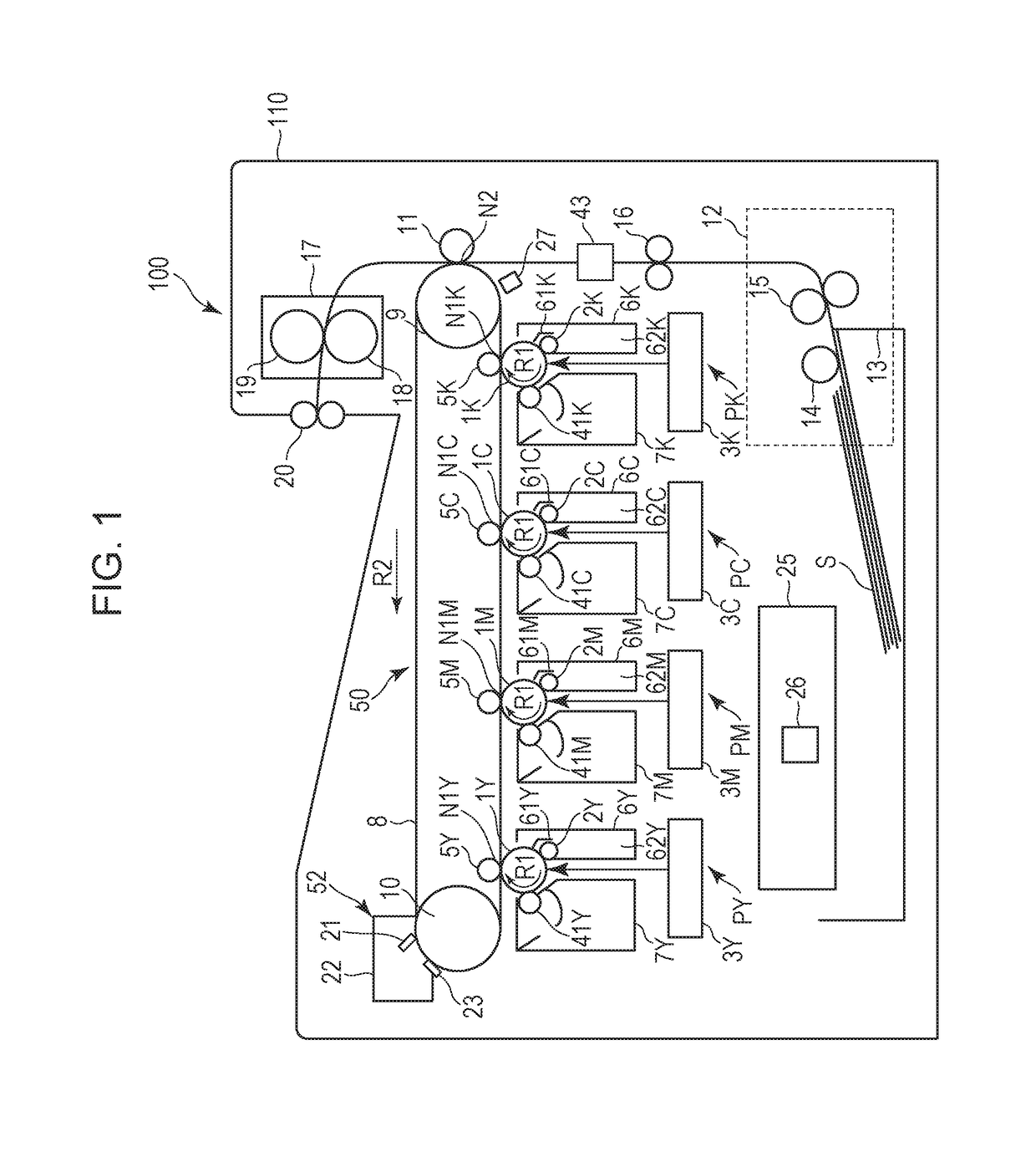
[0023]FIG. 1 illustrates a schematic configuration of an exemplary embodiment of an image forming apparatus according to the present disclosure. An image forming apparatus 100 of the present exemplary embodiment is an electrophotographic type full color printer employing an intermediate transfer system and an in-line system.

[0024]As a plurality of image forming unit, the image forming apparatus 100 includes four image forming units, namely, first, second, third, and fourth image forming units PY, PM, PC, and PK that form color images of yellow, magenta, cyan, and black, respectively. The four image forming units PY to PK are disposed in a line with uniform gaps therebetween.

[0025]Note that, in the present exemplary embodiment, other than the color of the toner used, the image forming units PY to PK have a lot in common in their configurations and operations. Accordingly, in the following description, when there is no particular nee...

second exemplary embodiment

[0103]Another exemplary embodiment of the present disclosure will be described next. Configuration and operation of an image forming apparatus of the present exemplary embodiment are the same as those of the first exemplary embodiment. Accordingly, elements that have the same or corresponding functions and configuration as those of the first exemplary embodiment will be attached with the same reference numerals and detailed description thereof will be omitted.

[0104]In the present exemplary embodiment, the photosensitive drums 1 of the image forming units that do not form an image are separated from the intermediate transfer belt 8 in monochrome mode. The above is more desirable since, compared with the first exemplary embodiment, the lifetime of the image forming units that do not form an image can be further suppressed from becoming short.

[0105]In the present exemplary embodiment, the general formation and the operation in full-color mode are the same as those of the first exemplar...


PUM


Abstract

An image forming apparatus including a cleaning member having a belt cleaning blade and a conductive brush. A value of a charging current that is generated when charging residual toner with the conductive brush is smaller when a color mode is executed compared to that when a monochrome mode is executed.

Description

BACKGROUND OF THE INVENTION[0001]Field of the Invention[0002]The present disclosure relates to image forming apparatuses, such as a copier, a printer, a facsimile machine, and a multifunctional printer that form images employing an electrophotographic method.[0003]Description of the Related Art[0004]In recent years, colorization in image forming apparatuses, such as a printer and a copier, is in progress. For example, as an image forming apparatus employing an electrophotographic method, the following image forming apparatus employing an intermediate transfer system and an in-line system is well known. That is, in the above image forming apparatus, a plurality of image forming units that each include an electrophotographic photoconductor (a photosensitive member) is disposed in a line on the surface of an intermediate transfer body in a moving direction of the intermediate transfer body. Furthermore, toner images with different colors formed on the photosensitive members of the imag...

Claims


Application Information

Patent Timeline
Patent Type & Authority Patents(United States)
IPC IPC(8): G03G15/08G03G15/16G03G21/00
CPCG03G15/161G03G21/0011G03G2215/0132G03G2221/001G03G2221/0073
Inventor YAGI, YASUTAKAFUNATANI, KAZUHIROFUJIMOTO, TETSUICHIROSEKI, HIROYUKIASAI, MASANORISAITO, SHUJI
Owner CANON KK
Learn More