Porous inlay for fuse housing

a fuse housing and porous inlay technology, applied in the field of porous inlay for fuse housing use, can solve the problems of low resistance current path between the fuse terminals, fuse not providing enough insulation resistance to protect the circuit components, chance or occurrence of carbon bridges

Active Publication Date: 2017-03-28
LITTELFUSE INC
View PDF27 Cites 2 Cited by
  • Summary
  • Abstract
  • Description
  • Claims
  • Application Information

AI Technical Summary

Problems solved by technology

This can lead to a low resistance current path between the fuse terminals.
As such, when a carbon bridge forms, the fuse does not provide enough insulation resistance to protect the circuit components.
Furthermore, as circuit voltage increases, so does the chance or occurrence of carbon bridges.
As will be appreciated, carbon bridges, and particularly the resulting leakage current, can damage circuit components intended to be protected by the melting of the fuse element.

Method used


Image

  • Porous inlay for fuse housing
  • Porous inlay for fuse housing
  • Porous inlay for fuse housing

Examples


Embodiment Construction

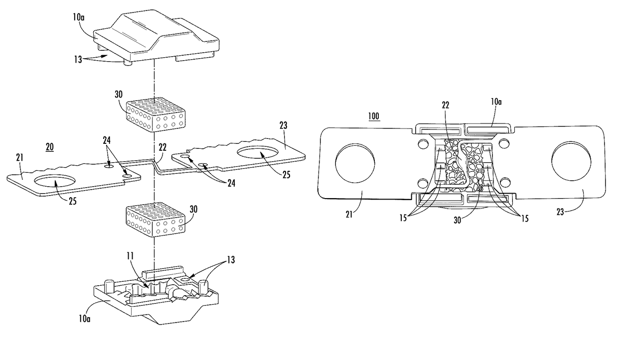
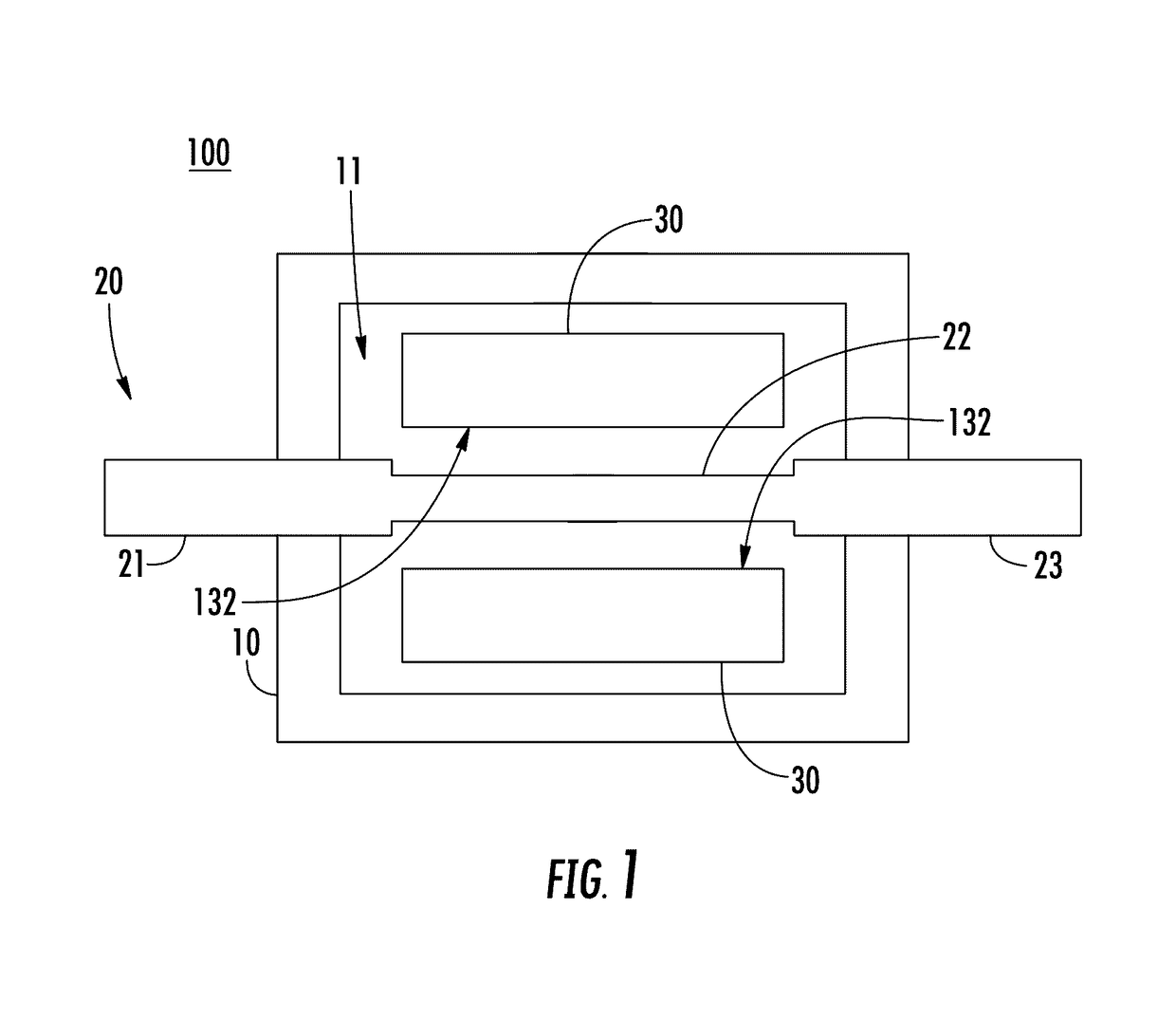
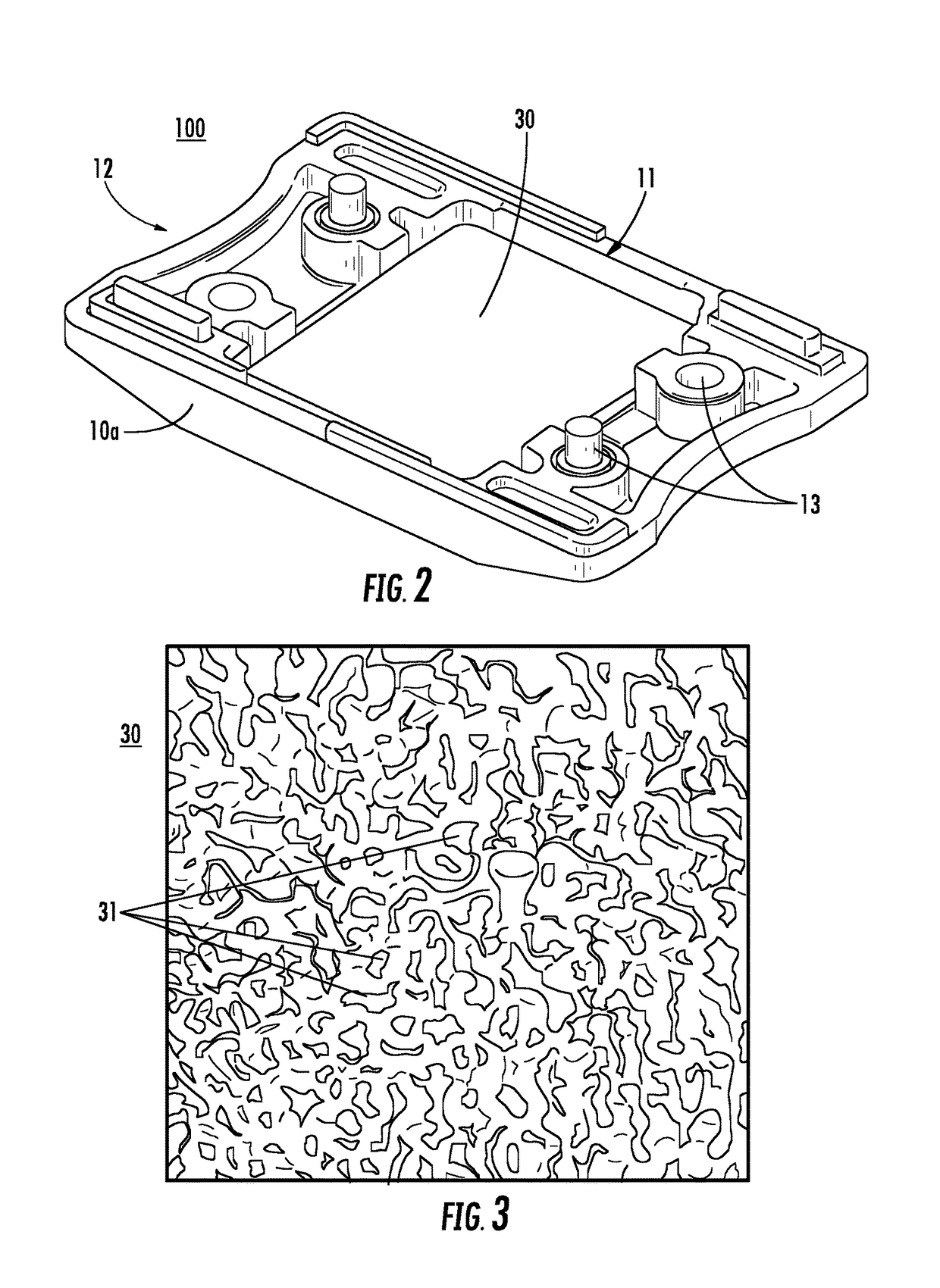
[0021]In general, the present disclosure provides a fuse having a housing disposed around a fuse element. The fuse further includes a porous material (e.g., silicone foam, or the like) disposed in the housing adjacent to the fuse element. During vaporization of the fuse element, portions of the vaporized fuse element may be captured in the pores of the porous material to prevent formation of carbon bridges. More specifically, the vaporized portions of the fuse element may be lodged in the pores of the porous material and thereby prevented from settling on the inside of the fuse housing and forming carbon bridges. As such, fuses according to the present disclosure may be provided having high insulation resistance (e.g., >1 MΩ at 70V for a 48V fuse, or the like) after melting of the fuse element. The example insulation resistance value given above is for purposes of clarity and completeness and is not intended to be limiting.

[0022]FIG. 1 is a block diagram of a fuse 100 according to e...


PUM

PropertyMeasurementUnit
pore sizeaaaaaaaaaa
pore sizeaaaaaaaaaa
insulation resistanceaaaaaaaaaa

Abstract

A fuse may include a housing having a cavity. The fuse may also include a fuse element disposed within the cavity; a plurality of terminals extending out of the housing and electrically connected to the fuse element; and porous material disposed in the cavity adjacent to the fuse element, the porous material having a plurality of pores, the porous material further comprising an open pore structure wherein at least some of the pores are disposed on an outer surface of the porous material facing the fuse element.

Description

RELATED APPLICATIONS[0001]This application claims priority to U.S. provisional patent application No. 62 / 001,924, filed May 22, 2014 and incorporated by reference herein in its entirety.FIELD OF THE DISCLOSURE[0002]This disclosure relates generally to the fuses and particularly to porous inlays for use in a fuse housing.BACKGROUND OF THE DISCLOSURE[0003]Fuses are commonly used as circuit protection devices. A fuse can provide electrical connections between sources of electrical power and circuit components to be protected. One type of fuse includes a fusible element disposed within a hollow fuse body. Conductive terminals may be connected to different ends of the fusible element through the fuse body to provide a means of connecting the fuse between a source of power and a circuit component.[0004]Upon the occurrence of a specified fault condition in a circuit, such as an overcurrent condition, the fusible element of a fuse may melt or otherwise separate to interrupt current flow in ...

Claims


Application Information

Patent Timeline
Patent Type & Authority Patents(United States)
IPC IPC(8): H01H85/05H01H69/02H01H85/175H01H85/38H01H85/00H01H85/18
CPCH01H85/05H01H69/02H01H85/175H01H85/1755H01H85/38H01H85/0086H01H85/18H01H2085/383H01H2085/388Y10T29/49108
Inventor SCHMIDT, FLORIANHOFMANN, MICHAELJUNG, PASCAL
Owner LITTELFUSE INC
Why Eureka
Try Eureka