Movement-resistant floor mat

a technology of floor mats and movement resistance, which is applied in the field of floor mats, can solve the problems of increased cleaning maintenance requirements, slip and fall of persons using the floor space, and the problem of floor surfaces of grocery stores that are often affected by movement, and achieve the effect of improving the resistance to movement of the floor ma

Active Publication Date: 2017-04-04
MMI ANDERSEN
View PDF10 Cites 0 Cited by
  • Summary
  • Abstract
  • Description
  • Claims
  • Application Information

AI Technical Summary

Benefits of technology

[0008]The present invention meets the needs in the art by providing a floor mat having a backing surface structure that provides improved resistant to movement of the floor mat during use by foot or wheeled traffic. The present invention provides a floor mat comprising a sheet having a first side and an opposing second side for disposing on a surface, the second side defining a plurality of spaced-apart lugs extending from the second side, each lug comprising a pair of opposing C-shaped nibs that each have a free distal end for disposing on a surface, the nibs of the pair spaced-apart to define a passage therebetween with a longitudinal axis in a selected direction of a plurality of directions, said selected direction different from the direction of the longitudinal axis of the passage in an adjacent lug.

Problems solved by technology

The uncaptured dirt and debris that dislodges after being carried into a floor space increases cleaning maintenance requirements and may lead to slip and falls by persons using the floor space.
Grocery stores often have problems arising with floor surfaces and traffic of persons walking on the floor surface and moving wheeled carts across the floor surfaces.
Some departments are susceptible to moisture on the floor.
In addition, other commercial facilities are similarly subject to moisture on the floor.
Notwithstanding, there are drawbacks to the use of currently available floor mats.
The loading of the traffic tends to cause the floor mat to “walk” or move slightly as the traffic moves across the mat.
The flex and return movement of the spikes tends to cause the floor mat to move.

Method used


Image

  • Movement-resistant floor mat
  • Movement-resistant floor mat
  • Movement-resistant floor mat

Examples


Embodiment Construction

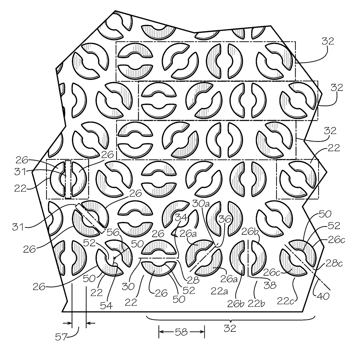
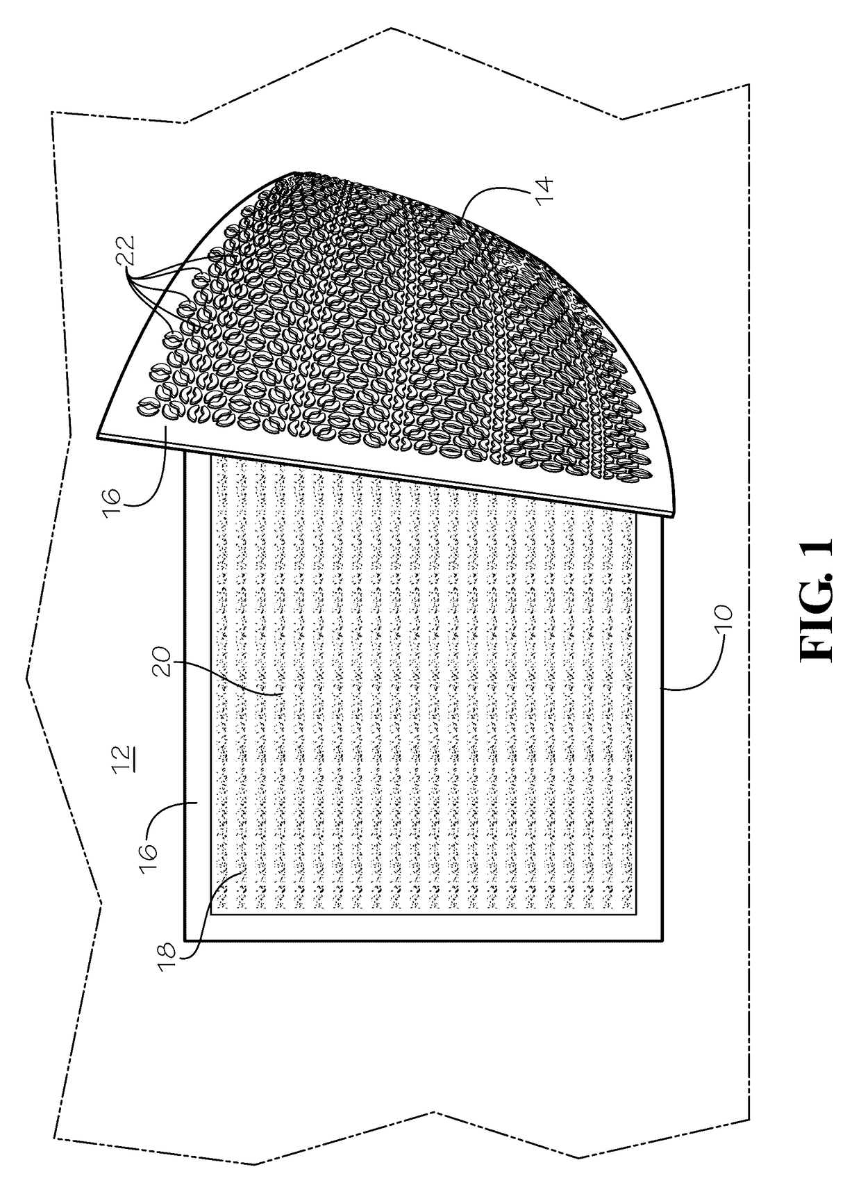
[0028]Referring now in more detail to the drawings in which like parts have like identifiers, FIG. 1 illustrates in perspective view a movement-resistant floor mat 10 according to the present invention placed on a floor surface 12 and a portion of the floor mat folded over to illustrate a bottom surface 14. The floor mat 10 may include a border 16. The illustrated embodiment includes as an upper surface 18 a fiber layer or carpet 20. In an alternate embodiment, the mat 10 may be a single rubber layer with a molded upper surface. The bottom surface 14 provides a backing for the mat 10, and includes a plurality of structures or lugs 22 that project from the back surface of the mat. The lugs 22 bear against the floor and cooperatively resist movement of the floor mat 10 during use of the mat in foot and wheeled cart traffic areas, as discussed below.

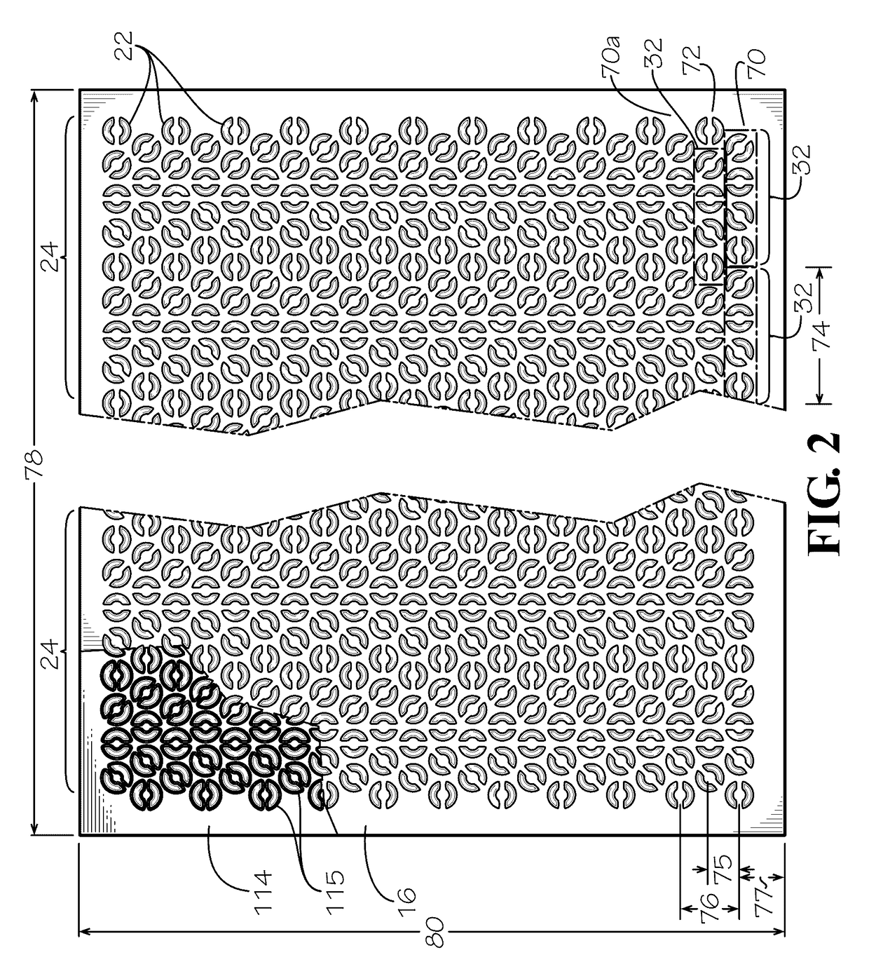
[0029]FIG. 2 illustrates in plan view the structure of the bottom surface 14 for the floor mat 10 and a cut-away illustrating a die 114 fo...


PUM

PropertyMeasurementUnit
radiusaaaaaaaaaa
radiusaaaaaaaaaa
radiusaaaaaaaaaa

Abstract

A floor mat made of a rubber sheet having a top surface and a bottom surface with spaced-apart lugs extending therefrom, each lug having a pair of opposing nibs spaced-apart to define a passage therebetween with a longitudinal axis in a selected direction and the selected direction different from the direction of the longitudinal axis of the passage in an adjacent lug, which lugs cooperatively resist movement of the mat in response to loading by foot and wheeled cart traffic across the floor mat disposed on a floor surface.

Description

TECHNICAL FIELD[0001]The present invention relates to floor mats. More particularly, the present invention relates to floor mats having a bottom surface with structural features that resist movement of the floor mat during use in foot and wheeled cart traffic areas.BACKGROUND OF THE INVENTION[0002]Commercial businesses, processing facilities, manufacturers, and homes often place floor mats at entrances and on aisle ways. The floor mats generally have a backing surface to bear against a floor surface and an opposing top surface for foot or wheeled traffic. The top surface may be molded or include a fabric or carpet for scraping debris from shoes and receiving and holding such dislodged debris. The floor mat may thus capture at least some of the dirt and debris that may otherwise be carried into a floor space and become dislodged there. The uncaptured dirt and debris that dislodges after being carried into a floor space increases cleaning maintenance requirements and may lead to slip ...

Claims


Application Information

Patent Timeline
Patent Type & Authority Patents(United States)
IPC IPC(8): B32B3/06A47G27/02B32B3/30B32B25/10B32B5/02
CPCA47G27/02B32B3/30B32B5/02B32B25/10B32B2250/02B32B2471/04A47G27/0281A47L23/266B32B25/04
Inventor TILLERY, WILLIAM LEON
Owner MMI ANDERSEN
Why Eureka
Try Eureka