Multiple clip wraparound hanger

a technology of garment straps and hangers, which is applied in the field of garment straps, can solve the problems of unsightly hanging down of/or the garment straps, difficult to repeat the process of secureing a large number of garments, and inability to attract attention and display the outer portion of the garment as well, so as to achieve greater flexibility for the insertion of garments, easy opening and use, and the effect of greater flexibility

Inactive Publication Date: 2011-03-01
PROSPERITY PROD HK LTD
View PDF8 Cites 20 Cited by
  • Summary
  • Abstract
  • Description
  • Claims
  • Application Information

AI Technical Summary

Benefits of technology

[0008]With this arrangement, as a garment is inserted into the second and third pairs of garment clips, it is easier for a worker to insert the garment and / or the garment strap between the first and second support members. Furthermore, the compound movement of each garment clip of the first pair of garment clips results in the garment receiving channel of the clip first opening to allow the garment to enter, and then closing to securely retain the garment therein. The center portion of the garment is displayed, while reducing the width of the display and advantageously increasing display density. However, the outer portions of the garment and / or the garment straps are advantageously secured behind the garment within a garment clip.
[0011]Furthermore, the second and third pairs of garment clips of the present invention are designed with a much greater flexibility, without a stiffening rib extending along the length of the first support member. The more flexible first support member is much easier to open and use, and provides greater flexibility for the insertion of garments. This greatly alleviates problems with carpel tunnel syndrome by persons who are employed to insert a great number of garments into a great number of such garment clips. To achieve this, the thickness and length of the first support member are different than the thickness and the length of the second support member. The first support member extends vertically down from the body and curves away from the second support member to define a second mouth. As the garment and / or garment strap enters the second mouth, the first support member begins to deflect in a direction into and out of a plane of the body. The second support member includes a substantially U-shaped member having a first free end and a second end integrally molded with the body. Because the second support member has a greater thickness than the first support member, the second support member is more resistant to movement into and out of the plane of the body. However, as the garment and / or garment strap moves further towards the body, the first free end of the U-shaped member deflects in a direction transverse to the plane of the body.

Problems solved by technology

However, the outer portion of the garment and / or the garment straps may hang down in an unsightly manner.
Although traditional clips secure the center portion of a wide garment, they fail to attractively secure and display the outer portions of the garment as well.
Furthermore, the inward clips of the prior art are substantially rigid and make it difficult to repetitiously secure a large number of garments.

Method used


Image

  • Multiple clip wraparound hanger
  • Multiple clip wraparound hanger
  • Multiple clip wraparound hanger

Examples


Embodiment Construction

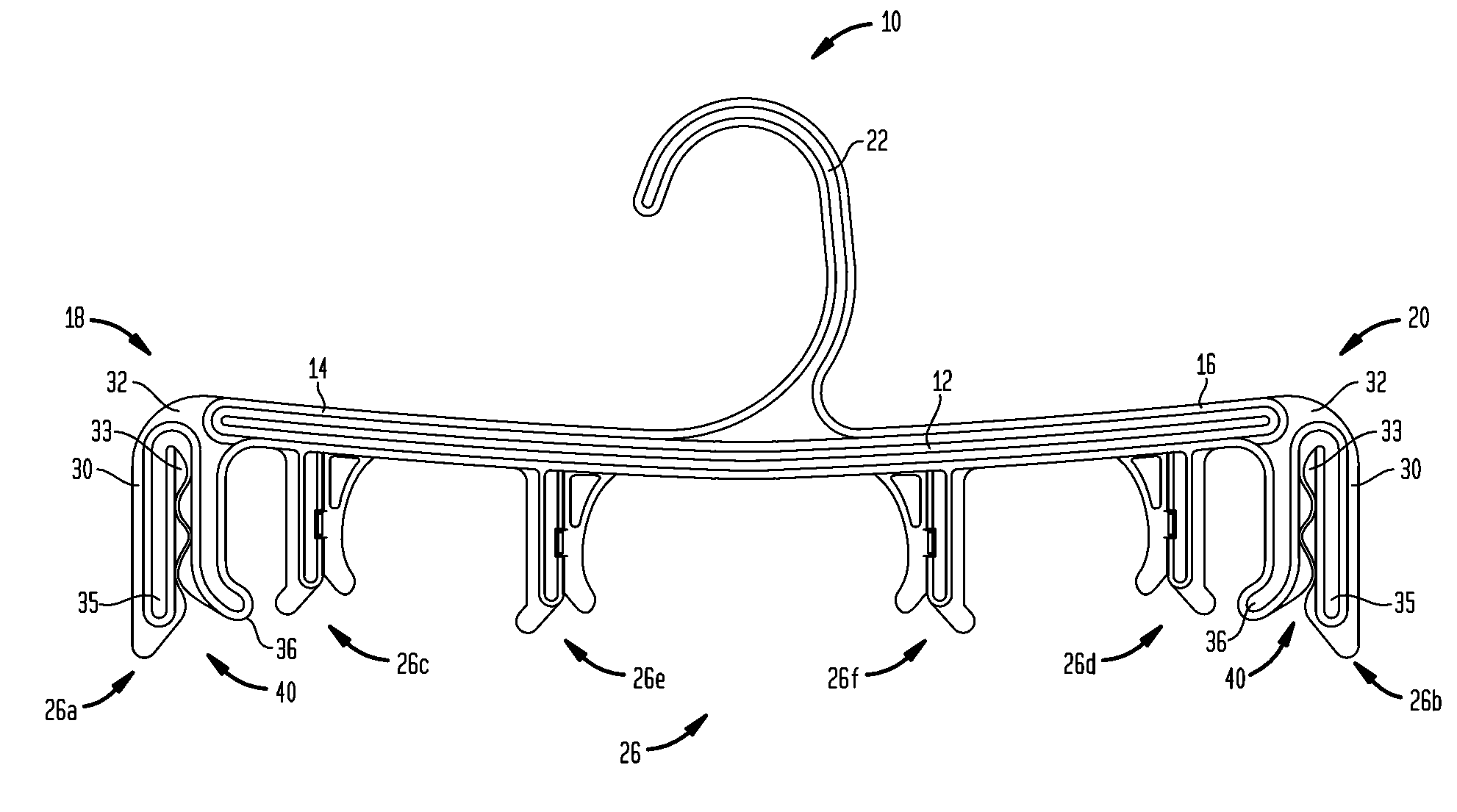
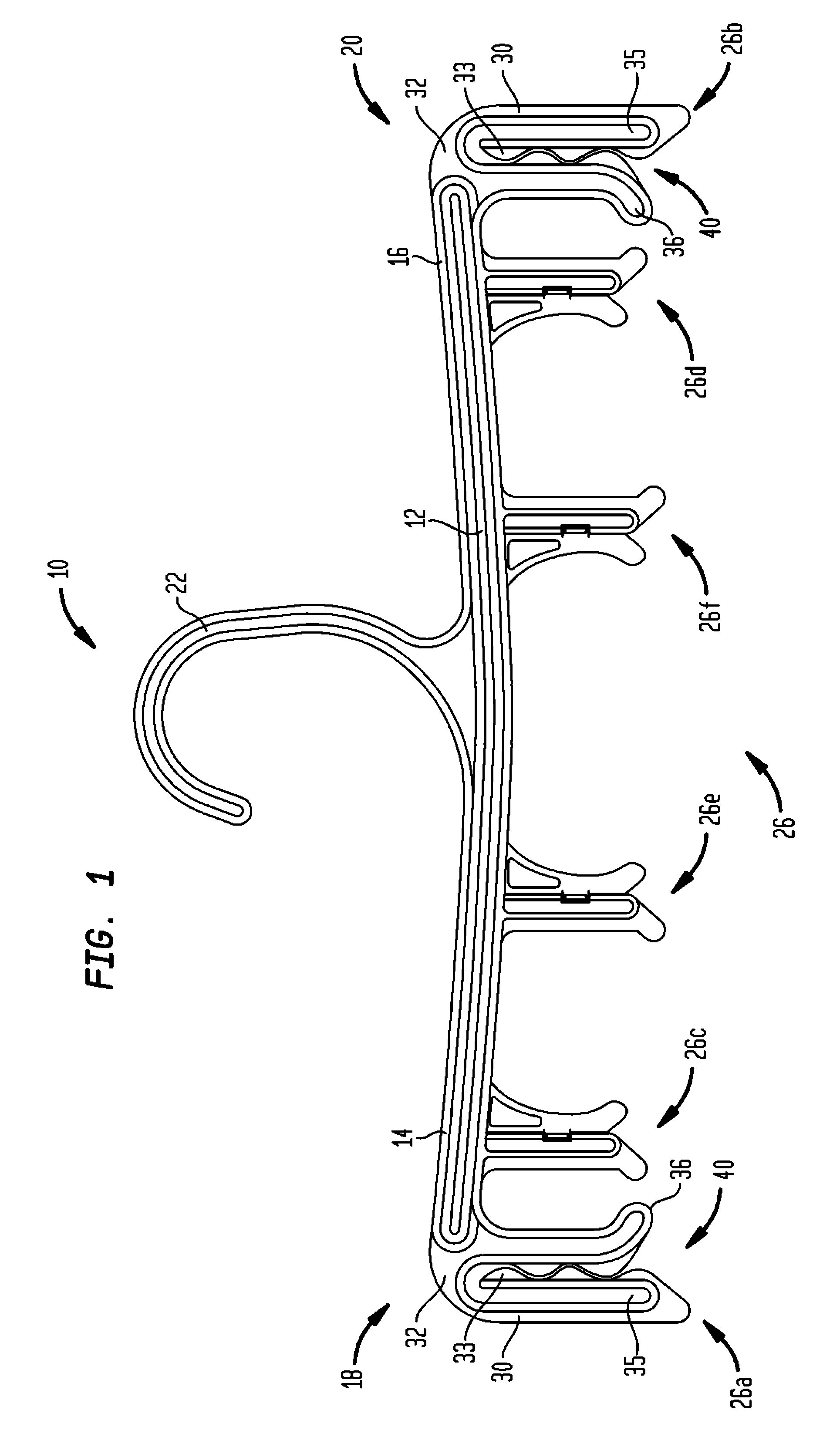
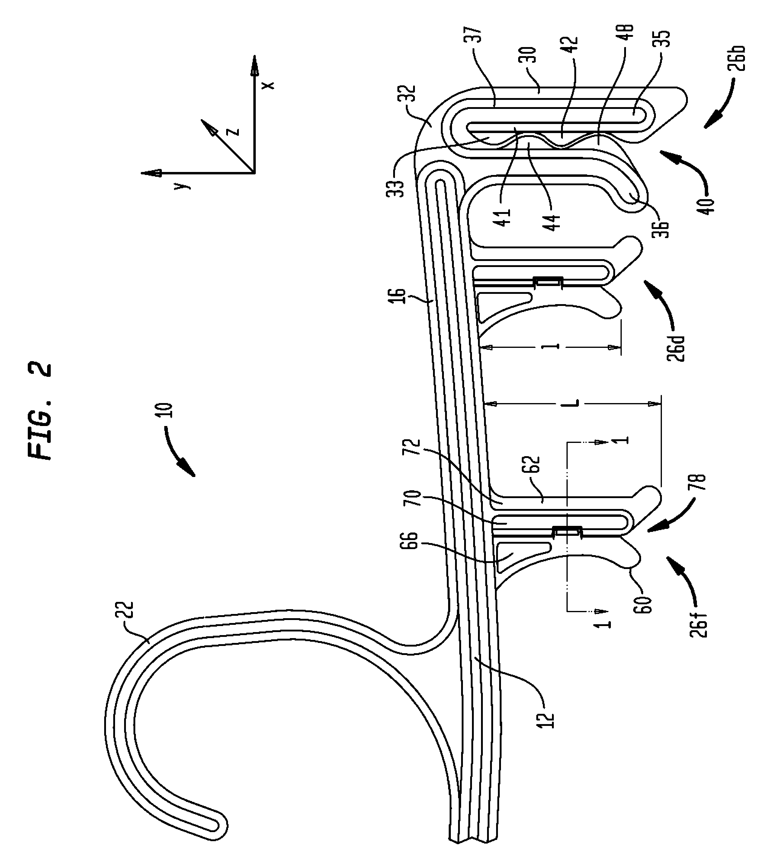
[0017]Referring now to FIGS. 1 and 2, illustrated is a multiple clip garment hanger (hereinafter “garment hanger”) 10 according to a first embodiment of the present invention. Garment hanger 10 has a body 12, with a first arm 14 and a second arm 16 extending laterally outward in opposing directions to respective first and second ends 18, 20. A hook 22 extends upward from the body 12 for suspending the garment hanger 10 from a support (not shown). The particular illustrated shapes of the central hook member 12 and the first and second arms 14, 16 are exemplary only, and may vary in number and shape.

[0018]As shown in FIGS. 1-2, a plurality of garment clips 26 are secured to the garment hanger 10, and are optionally integrally molded with the body 12 and / or arms 14, 16. A first pair of garment clips 26a, 26b are secured to the first and second arms 14, 16 at the first and second ends 18, 20, respectively. A second pair of garment clips 26c, 26d are secured to the garment hanger body 12...


PUM


Abstract

The present invention is a multiple clip wraparound garment hanger with a body having a first arm and a second arm extending laterally outward in opposing directions to a first end and a second end, and a hook extending upward from the body for suspending the garment hanger from a support. A first pair of garment clips is secured to the first and second arms at the first and second ends, respectively. A second pair of garment clips is secured to the body inward of the first and second ends, and a third pair of garment clips secured to the body inward of the second pair of clips. The second and third pairs of garment clips have a first support member and a second support member, each support member having a different thickness. The first support member is substantially flexible and permits deflection of the first support member in a direction into and out of a plane of the body.

Description

BACKGROUND OF THE INVENTION[0001]1. Field of Invention[0002]The present invention relates to the field of garment hangers, and more specifically to a garment hanger having multiple clips for attractively securing and displaying a garment.[0003]2. Description of Related Art[0004]Wraparound garment hangers are so named because a garment wider than the garment hanger, typically but not exclusively women's undergarments or swimsuit bottoms, is wrapped around the garment hanger and held by clips at the ends of the garment hanger. Therefore, the center portion of the garment is displayed, while reducing the width of the display and advantageously increasing display density. However, the outer portion of the garment and / or the garment straps may hang down in an unsightly manner.[0005]Accordingly, additional inward clips were added to certain prior art wraparound garment hangers to hold portions of the garment behind the center portion on display. Although traditional clips secure the cente...

Claims


Application Information

Patent Timeline
Patent Type & Authority Patents(United States)
IPC IPC(8): A41D27/22
CPCA47G25/50A47G25/488
Inventor GOULDSON, STANLEY F.
Owner PROSPERITY PROD HK LTD
Why Eureka
Try Eureka