Optical fiber screening test method and optical fiber screening test apparatus
a technology of optical fiber and test apparatus, which is applied in the direction of instruments, structural/machine measurement, thin material processing, etc., can solve the problems of defective products being manufactured, optical fiber on the winding bobbin may be damaged, performance deterioration, etc., to prevent fiber beating, increase equipment cost, and prevent the effect of deterioration
- Summary
- Abstract
- Description
- Claims
- Application Information
AI Technical Summary
Benefits of technology
Problems solved by technology
Method used
Image
Examples
first embodiment
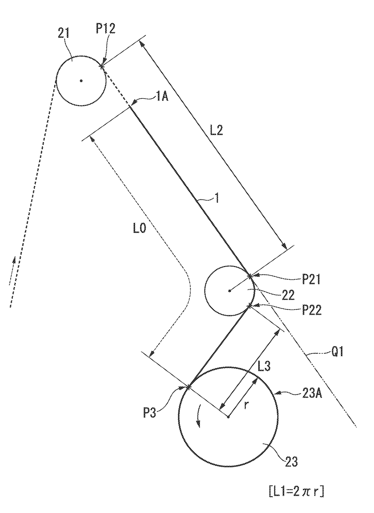
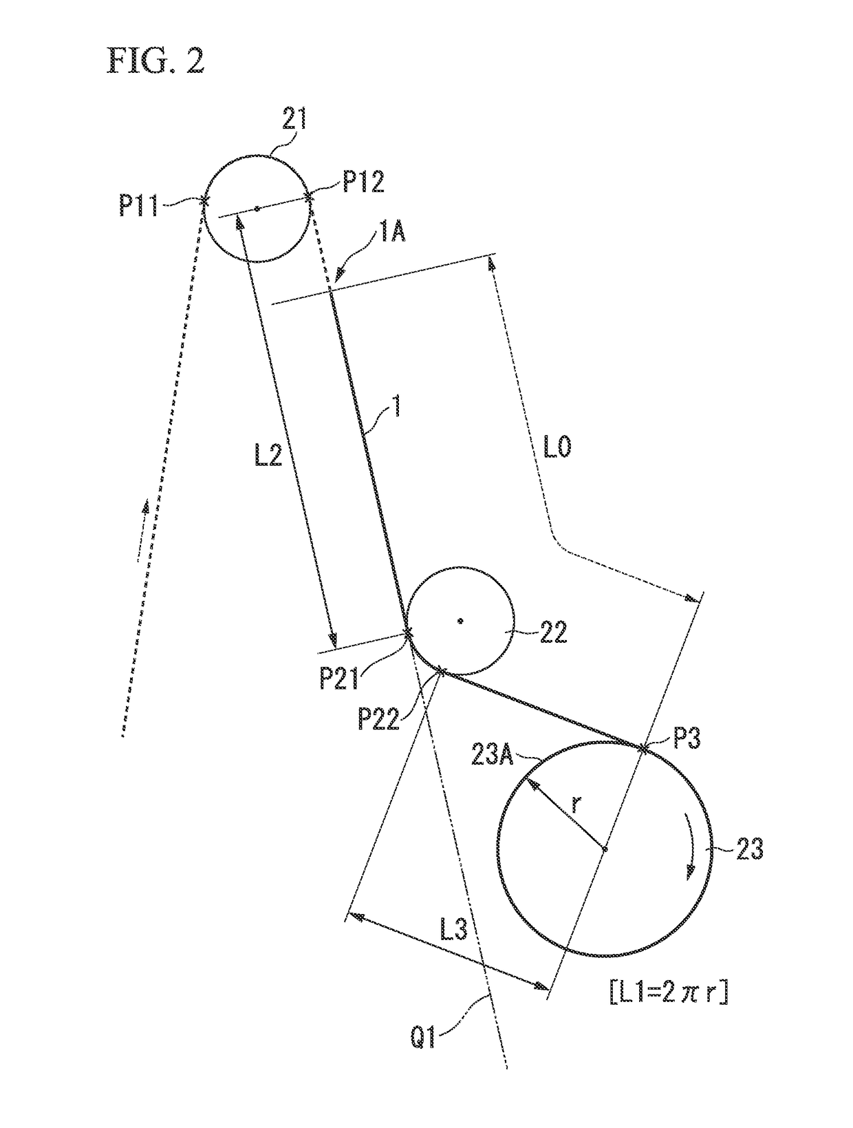
[0055]FIG. 2 shows a first implementation state of an optical fiber screening test method in the present invention, and particularly, a state at the time when the rotation of the winding bobbin 23 is stopped after the optical fiber is broken.
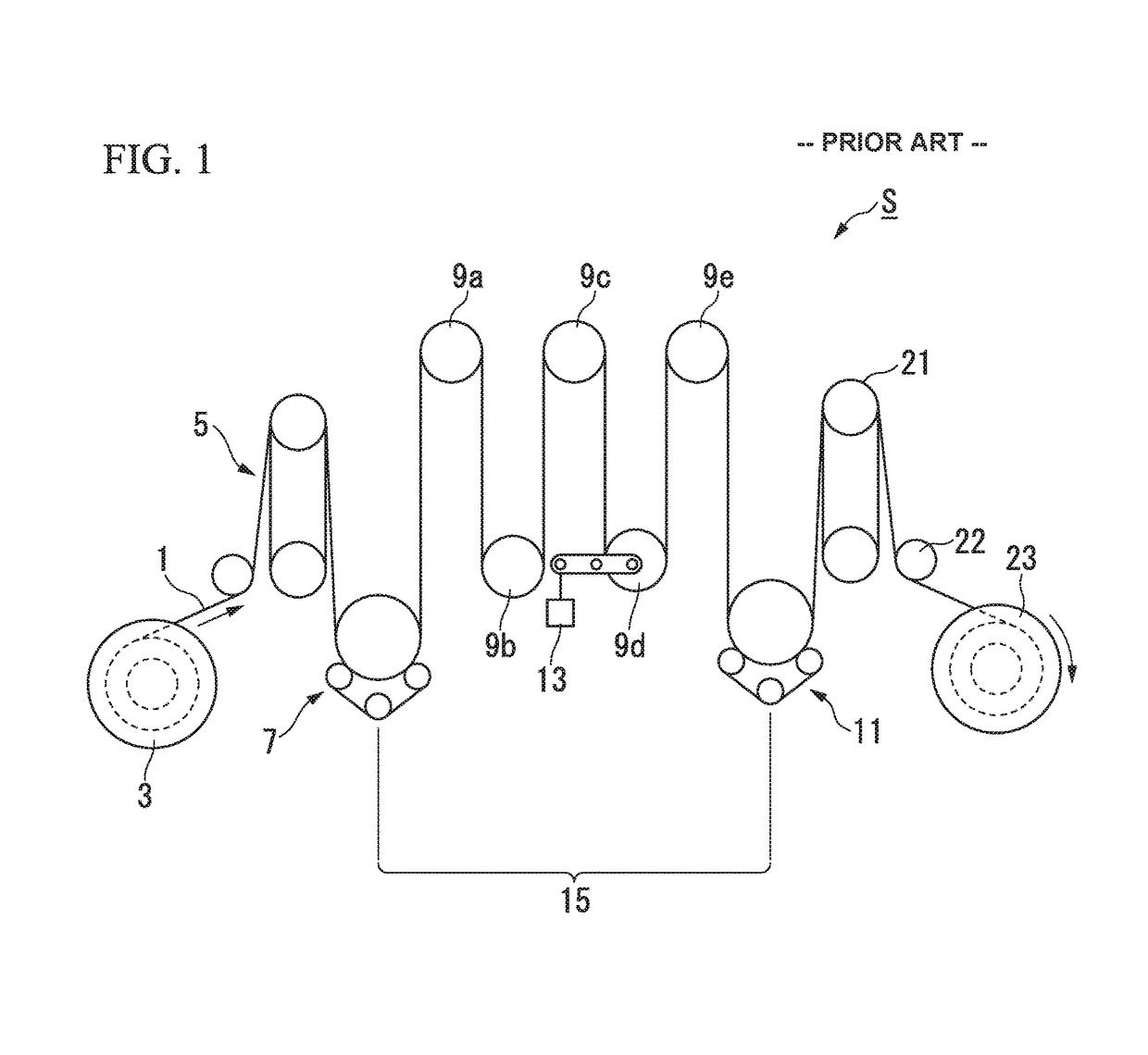
[0056]In FIG. 2, only parts of the first pulley 21, the second pulley 22, and the winding bobbin 23 in the screening test apparatus S shown in FIG. 1 are shown. The entire configuration of the screening test apparatus S may be the same as the configuration shown in FIG. 1. However, the entire configuration of the screening test apparatus is not limited to the configuration shown in FIG. 1, and the configuration has the tension applying section 15 that applies tension to the optical fiber 1 for the screening test during the continuous travelling of the optical fiber 1, and the first pulley 21, the second pulley 22, and the winding bobbin 23 may be arranged on a downstream side of the tension applying section 15 in order.
[0057]The position of the ...
first embodiment (figs.2 and 3)
[0096]First Embodiment (FIGS. 2 and 3)
[0097]A case in which the rotation center of the first pulley 21 and the rotation center of the second pulley 22 are positioned on opposite sides from each other with respect to the travelling path of the optical fiber 1, and the rotation center of the second pulley 22 and the rotation center of the winding bobbin 23 are positioned on opposite sides from each other with respect to the travelling path of the optical fiber 1.
[0098]In this case, the linear travelling path (the length L2) from the surface of the first pulley 21 on which the optical fiber is wrapped to the surface of the second pulley 22 on which the optical fiber is wrapped corresponds to the internal common tangent between the wrapping surface of the first pulley 21 and the second pulley 22.
[0099]In addition, the linear travelling path (the length L3) from the wrapping surface of the second pulley 22 to the already-wound outer circumferential surface 23A of the winding bobbin 23 co...
second embodiment (fig.4)
[0100]Second Embodiment (FIG. 4)
[0101]A case in which the rotation center of the first pulley 21 and the rotation center of the second pulley 22 are positioned on the same side with respect to the travelling path of the optical fiber 1, and the rotation center of the second pulley 22 and the rotation center of the winding bobbin 23 are positioned on the opposite sides from each other with the travelling path of the optical fiber 1 interposed therebetween.
[0102]In this case, the linear travelling path (the length L2) from the surface of the first pulley 21 on which the optical fiber is wrapped to the surface of the second pulley 22 on which the optical fiber is wrapped corresponds to an external common tangent between the wrapping surface of the first pulley 21 and the second pulley 22.
[0103]In addition, the linear travelling path (the length L3) from the wrapping surface of the second pulley 22 to the already-wound outer circumferential surface 23A of the winding bobbin 23 correspon...
PUM
 Abstract
Description
Claims
Application Information
 - R&D
- Intellectual Property
- Life Sciences
- Materials
- Tech Scout
- Unparalleled Data Quality
- Higher Quality Content
- 60% Fewer Hallucinations
Browse by: Latest US Patents, China's latest patents, Technical Efficacy Thesaurus, Application Domain, Technology Topic, Popular Technical Reports.
© 2025 PatSnap. All rights reserved.Legal|Privacy policy|Modern Slavery Act Transparency Statement|Sitemap|About US| Contact US: help@patsnap.com


