
Key switch and keyboard

a key switch and keyboard technology, applied in the field of switch configuration, can solve the problems of affecting the accuracy of the opening or closing action of the contact, the deterioration of the key operation properties of the key top, and the deterioration of the keying operability of each key switch or the touch feeling of the finger, so as to prevent foreign matter reliably and stably.

Inactive Publication Date: 2008-01-10
FUJITSU COMPONENENT LTD
View PDF3 Cites 47 Cited by
  • Summary
  • Abstract
  • Description
  • Claims
  • Application Information

AI Technical Summary

Benefits of technology

The present invention provides a key switch with a protection function that prevents foreign matter from penetrating its internal structure. The key switch includes a pair of link members that support and direct the key top in a vertical direction relative to the base section. The switch member includes a contact section capable of opening and closing in response to the vertical movement of the key top. A biasing member applies an elastic biasing force in a vertically upward direction to the key top. A link support member attached to the key top pivotably supports the pair of link members. The link support member includes a major plate portion and a pair of opposing wall portions with bearing holes for receiving the pivoting axles of the link members. The key switch also includes a light-shielding member that prevents light emitted from a light-emitting section from escaping. The invention also provides a keyboard comprising a plurality of key switches.

Problems solved by technology

However, due to the existence of the cover member, the keying operability for each key switch or the touch feeling of a finger may be deteriorated.
If foreign matter, such as dust, liquid, etc., penetrates the movable sections of the link members or the engaging portions between the base section and the link members, the keying operation properties of the key top may be affected, and, if foreign matter penetrates the interacting portion between the contact section of the switch member and the actuating member, the accuracy of the opening or closing action of the contact may be deteriorated.
Further, a relatively large amount of application force may damage the pivot support section.

Method used


Image

  • Key switch and keyboard
  • Key switch and keyboard
  • Key switch and keyboard

Examples


Embodiment Construction

[0051]The embodiments of the present invention are described below in detail, with reference to the accompanying drawings. In the drawings, the same or similar components are denoted by common reference numerals.

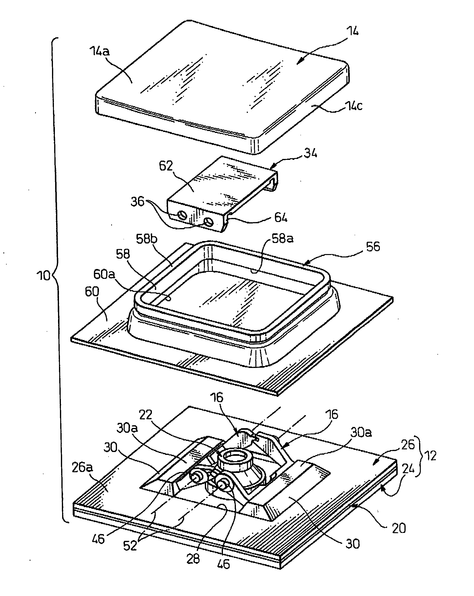
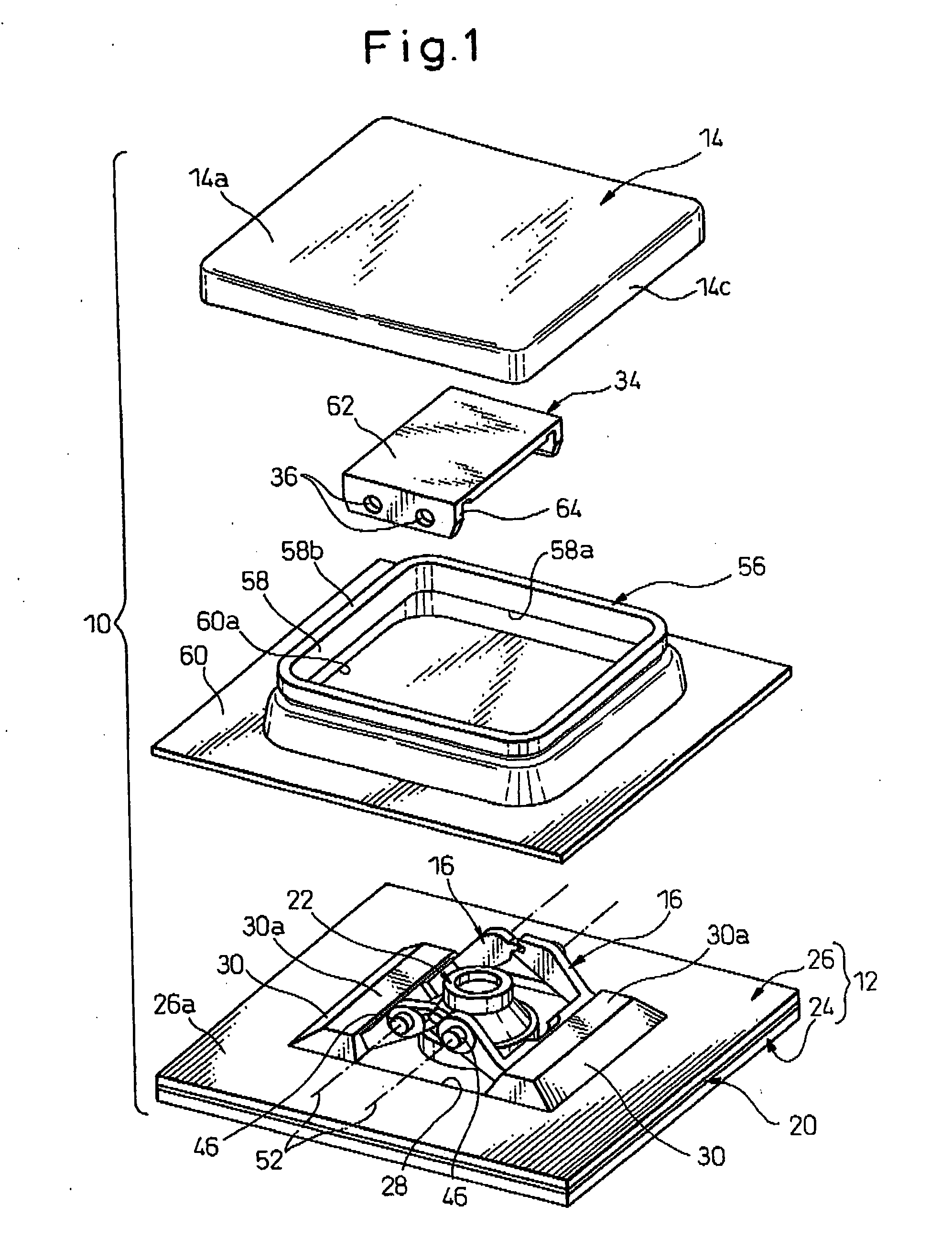
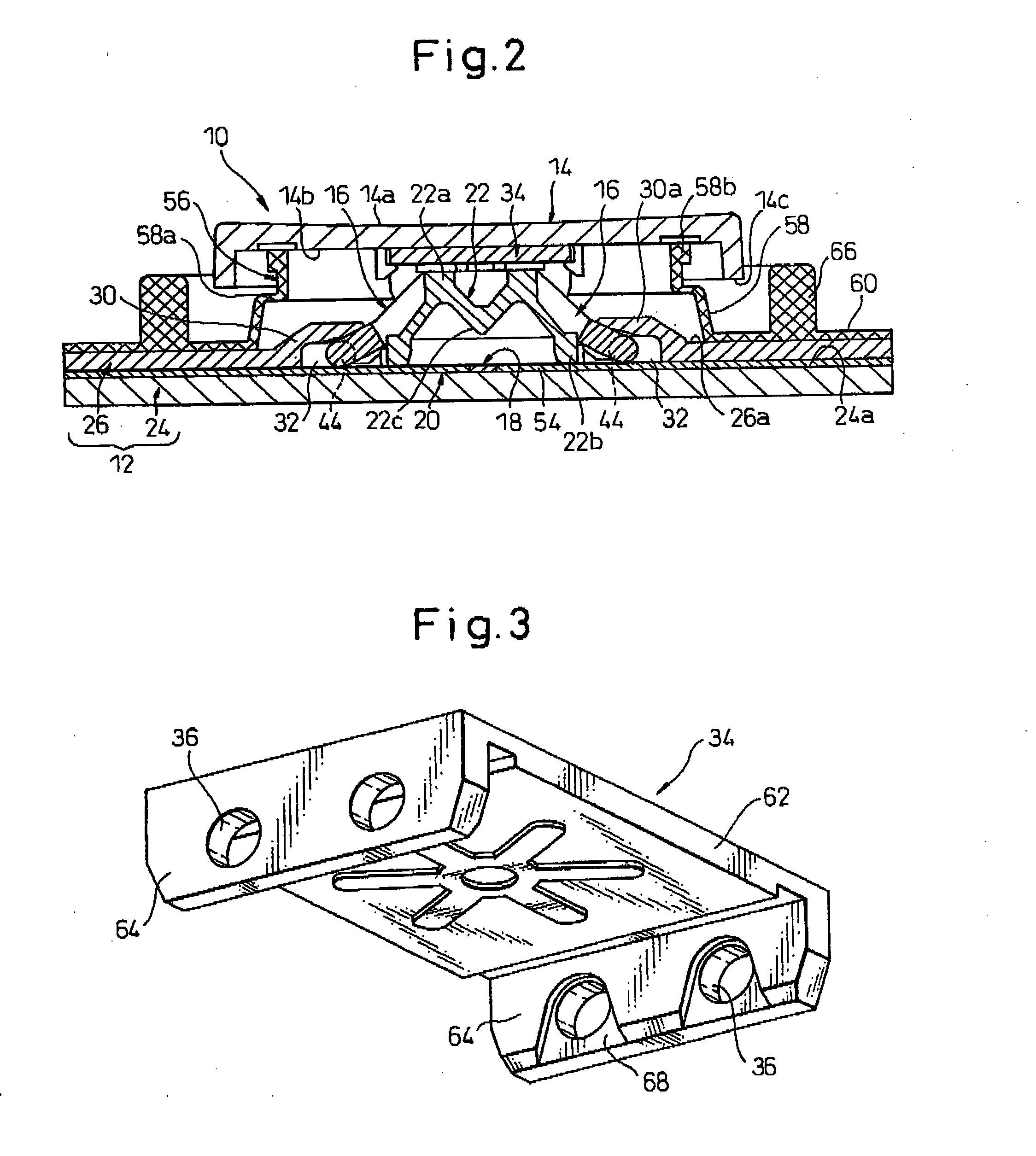
[0052]Referring to the drawings, FIG. 1 is an exploded perspective view showing a key switch 10 according to an embodiment of the present invention; FIG. 2 is a sectional view showing the key switch 10 in an assembled and non-operated state; FIGS. 3 and 4 are enlarged views of various components of the key switch 10; and FIG. 5 is a sectional view showing the key switch 10 in an assembled and operated state. The key switch 10 can be preferably used for a thin or low-profile keyboard provided in a portable electronic apparatus such as a notebook or palmtop personal computer and the like.

[0053]As shown in FIGS. 1 and 2, the key switch 10 includes a base section 12; a key top 14 disposed above the base section 12; a pair of link members 16 interlocked to each other to support a...


PUM


Abstract

A key switch preferably used for a keyboard as an input device in electronic equipment. The key switch includes a base section; a key top disposed above the base section; a pair of link members interlocked to each other to support and direct the key top in a vertical direction relative to the base section; a switch member including a contact section capable of opening and closing in response to a vertical movement of the key top; and a biasing member capable of applying an elastic biasing force in a vertically upward direction to the key top. The key switch further includes a protection member disposed and inserted between the base section and the key top at a position where the protection member surrounds the pair of link members, the contact section and the biasing member. The protection member is elastically deformed to follow the vertical movement of the key top, and protects the pair of link members, the contact section and the biasing member from penetration of foreign matter.

Description

BACKGROUND OF THE INVENTION[0001]1. Field of the Invention[0002]The present invention relates generally to a switch configuration for a keying operation, and more particularly to a key-entry switch device (hereinafter referred to as a key switch) preferably used for a keyboard incorporated as an input device in electronic equipment. The present invention also relates to a keyboard provided with a plurality of key switches.[0003]2. Description of the Related Art[0004]In a thinner or low-profile type keyboard, equipped for a portable electronic apparatus such as a notebook or palm-top personal computer, it is required to reduce the height of a key switch for a keying operation as well as to improve the operability and structural reliability of the key switch. The key switch usable in the low-profile keyboard typically includes a base section, a key top disposed above the base section, a pair of link members interlocked to each other to support and direct the key top in an upward-and-d...

Claims


Application Information

Patent Timeline
Patent Type & Authority Applications(United States)
IPC IPC(8): H01H13/70
CPCH01H3/122H01H13/702H01H2209/082H01H2223/002H01H2219/064H01H2221/07H01H2219/014
Inventor NISHINO, TAKESHIMARUYAMA, JUNICHINAKAMURA, SHUJI
Owner FUJITSU COMPONENENT LTD
Learn More