Optical fiber screening test method and optical fiber screening test apparatus

a technology of optical fiber and test apparatus, which is applied in the direction of instruments, structural/machine measurement, thin material processing, etc., can solve the problems of defective products being manufactured, optical fiber on the winding bobbin may be damaged, performance deterioration, etc., to prevent fiber beating, increase equipment cost, and prevent the effect of deterioration

Active Publication Date: 2014-09-11
THE FUJIKURA CABLE WORKS LTD
View PDF5 Cites 2 Cited by
  • Summary
  • Abstract
  • Description
  • Claims
  • Application Information

AI Technical Summary

Benefits of technology

[0044]According to the screening test method and the apparatus of the present invention, when the optical fiber is subjected to the screening test, it is possible to reliably and stably prevent the phenomenon that when the low-strength portion of the optical fiber is broken during the screening test of the optical fiber, the terminal portion of the ruptured end of the optical fiber collides with the optical fiber which has been already wound around the winding bobbin with the rotation stop of the winding bobbin to damage or deteriorate the already-wound optical fiber, that is, the fiber beating from occurring. Further, the fiber beating can be prevented while extension of the pass line, an increase in the cost of equipment, and difficulty in application to an existing screening test apparatus are prevented.

Problems solved by technology

When the fiber beating occurs, the optical fiber which has been already wound around the winding bobbin 23 is damaged or the performance is deteriorated, and thus, there is a concern that a defective product may be manufactured.
Therefore, an impact of the above-described fiber beating is large and thus, there is a very high concern that the optical fiber on the winding bobbin may be damaged when the fiber beating occurs.
Therefore, the rotation of the winding bobbin cannot be stopped in most cases before the ruptured end reaches the winding bobbin, and as a result, the frequency of fiber beating increases.
H10-114537, actually, it is difficult to reliably prevent fiber beating from occurring.
Therefore, there is a possibility of fiber beating occurring.
H10-114537 is actually applied, extension of the pass line is caused, and the size of equipment and the cost of equipment increase.
Further, since it is necessary to extend the pass line, it is difficult to apply the method to an existing screening test apparatus.
However, even according to the technique proposed in Japanese Unexamined Patent Application, First Publication No. 2004-59243, it is difficult to reliably and stably prevent fiber beating.
However, the fiber beating caused by the inertial force in the rotation direction cannot be prevented in the technique disclosed in Japanese Unexamined Patent Application, First Publication No. 2004-59243.
In addition, when the technique disclosed in Japanese Unexamined Patent Application, First Publication No. 2004-59243 is applied to an existing screening test apparatus, it is difficult to add the fiber beating preventing cover.
H10-114537, it is difficult to prevent the fiber beating from occurring.
However, the technique does not always reliably prevent the fiber beating and further, the fiber beating caused by the third phenomenon, that is, the fiber beating caused by the inertial force of the optical fiber in the rotation direction of the winding bobbin at the time when the rotation of the winding bobbin is stopped cannot be prevented.

Method used


Image

  • Optical fiber screening test method and optical fiber screening test apparatus
  • Optical fiber screening test method and optical fiber screening test apparatus
  • Optical fiber screening test method and optical fiber screening test apparatus

Examples


first embodiment

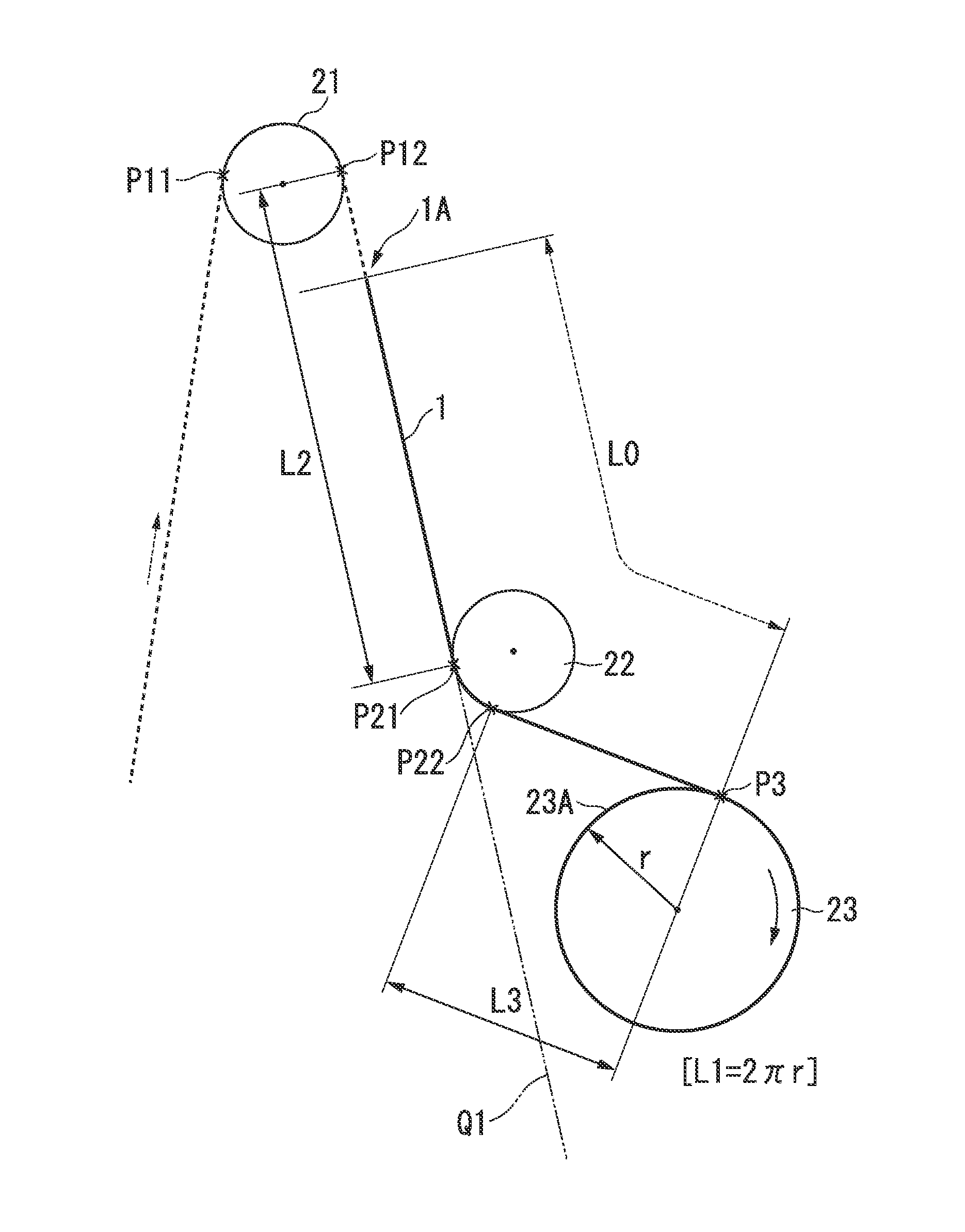
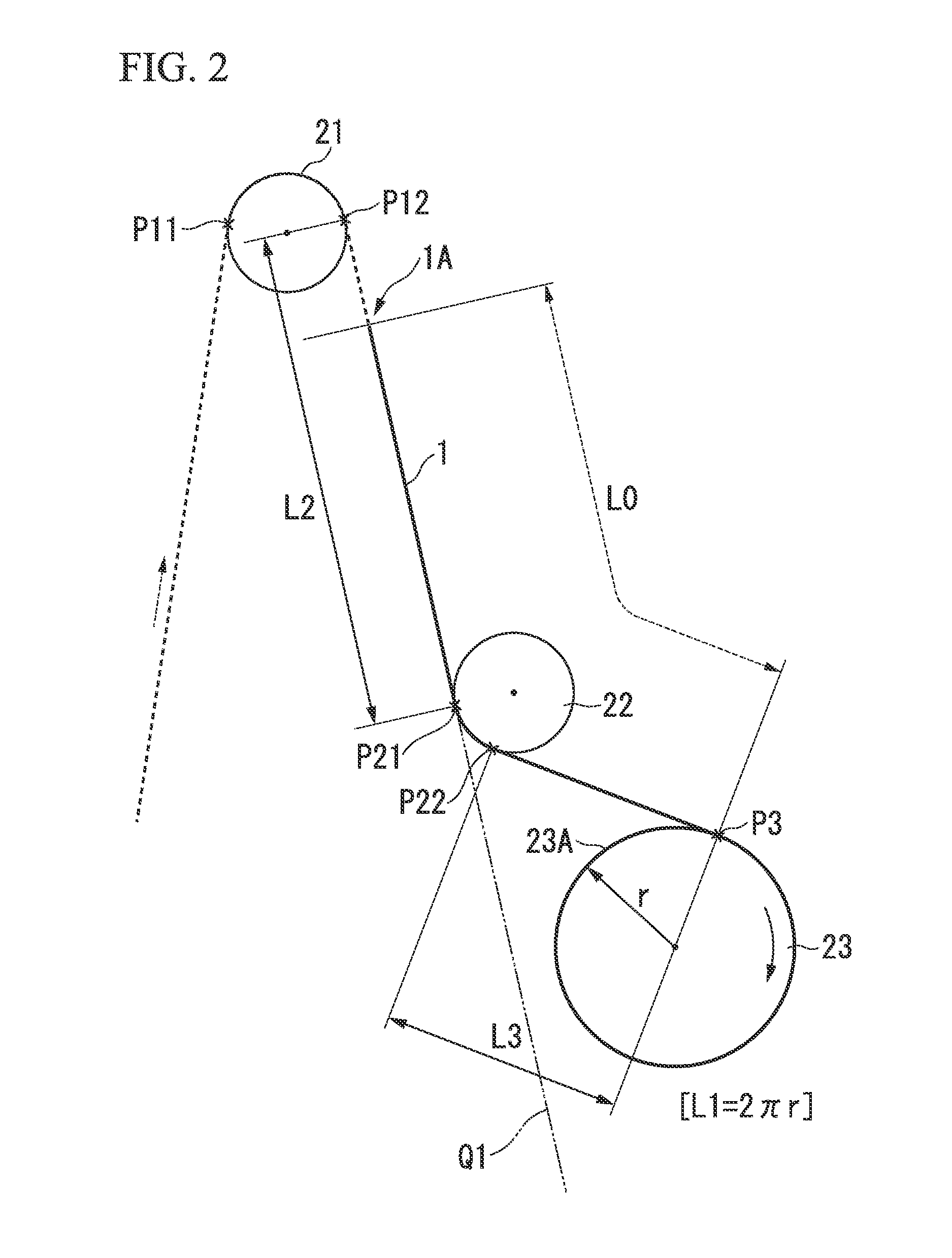
[0055]FIG. 2 shows a first implementation state of an optical fiber screening test method in the present invention, and particularly, a state at the time when the rotation of the winding bobbin 23 is stopped after the optical fiber is broken.

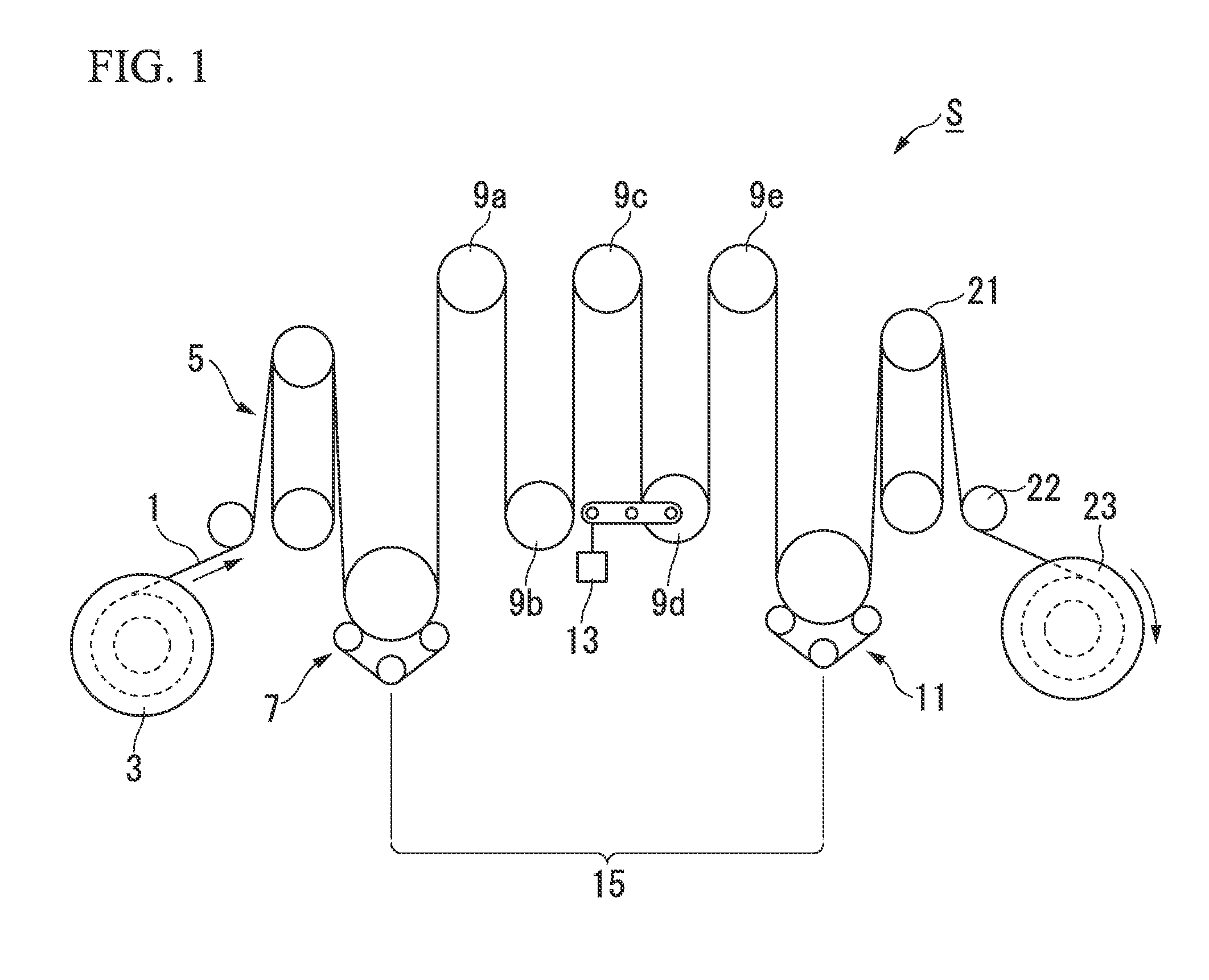
[0056]In FIG. 2, only parts of the first pulley 21, the second pulley 22, and the winding bobbin 23 in the screening test apparatus S shown in FIG. 1 are shown. The entire configuration of the screening test apparatus S may be the same as the configuration shown in FIG. 1. However, the entire configuration of the screening test apparatus is not limited to the configuration shown in FIG. 1, and the configuration has the tension applying section 15 that applies tension to the optical fiber 1 for the screening test during the continuous travelling of the optical fiber 1, and the first pulley 21, the second pulley 22, and the winding bobbin 23 may be arranged on a downstream side of the tension applying section 15 in order.

[0057]The position of the ...

first embodiment (

FIGS. 2 and 3)

[0096]A case in which the rotation center of the first pulley 21 and the rotation center of the second pulley 22 are positioned on opposite sides from each other with respect to the travelling path of the optical fiber 1, and the rotation center of the second pulley 22 and the rotation center of the winding bobbin 23 are positioned on opposite sides from each other with respect to the travelling path of the optical fiber 1.

[0097]In this case, the linear travelling path (the length L2) from the surface of the first pulley 21 on which the optical fiber is wrapped to the surface of the second pulley 22 on which the optical fiber is wrapped corresponds to the internal common tangent between the wrapping surface of the first pulley 21 and the second pulley 22.

[0098]In addition, the linear travelling path (the length L3) from the wrapping surface of the second pulley 22 to the already-wound outer circumferential surface 23A of the winding bobbin 23 corresponds to the interna...

second embodiment (fig.4)

Second Embodiment (FIG. 4)

[0099]A case in which the rotation center of the first pulley 21 and the rotation center of the second pulley 22 are positioned on the same side with respect to the travelling path of the optical fiber 1, and the rotation center of the second pulley 22 and the rotation center of the winding bobbin 23 are positioned on the opposite sides from each other with the travelling path of the optical fiber 1 interposed therebetween.

[0100]In this case, the linear travelling path (the length L2) from the surface of the first pulley 21 on which the optical fiber is wrapped to the surface of the second pulley 22 on which the optical fiber is wrapped corresponds to an external common tangent between the wrapping surface of the first pulley 21 and the second pulley 22.

[0101]In addition, the linear travelling path (the length L3) from the wrapping surface of the second pulley 22 to the already-wound outer circumferential surface 23A of the winding bobbin 23 corresponds to ...


PUM


Abstract

An optical fiber screening test method in which while continuously travelling, an optical fiber passes a tension applying section which applies tension and the optical fiber which has passed the tension applying section is continuously wound by a winding bobbin is provided. The method includes running the optical fiber to which the tension has been applied along a first pulley and a second pulley sequentially, winding the optical fiber by the winding bobbin, and stopping rotation of the winding bobbin when the optical fiber is broken by applying the tension, and performing an adjustment so that an already-wound outer circumferential surface of the winding bobbin on which the optical fiber is already wound is not positioned on an extension line of a linear optical fiber travelling path from the first pulley to the second pulley at a time when the rotation of the winding bobbin is stopped.

Description

CROSS REFERENCE TO RELATED APPLICATIONS[0001]Priority is claimed on Japanese Patent Application No. 2013-045713, filed on Mar. 7, 2013, the contents of which are incorporated herein by reference.BACKGROUND OF THE INVENTION[0002]1. Field of the Invention[0003]The present invention relates to a screening test method and a screening test apparatus used to detect a low-strength portion in an optical fiber.[0004]2. Description of Related Art[0005]In a process of manufacturing an optical fiber, in order to ensure the strength of the optical fiber to be shipped as a product, while the optical fiber travels continuously in the final manufacturing stage, a tensile test is continuously conducted by applying tension to the optical fiber to break a low-strength portion and remove the broken optical fiber or the vicinity of the broken portion. This type of continuous tensile test is referred to as a screening test.[0006]As a typical example of the screening test apparatus, for example, there has...

Claims


Application Information

Patent Timeline
Patent Type & Authority Applications(United States)
IPC IPC(8): B65H63/036
CPCB65H63/036B65H2701/32G01M11/088
Inventor YAMADA, NARITOSHI
Owner THE FUJIKURA CABLE WORKS LTD
Why Eureka
Try Eureka