
Distributed autonomous system and method for controlling distributed autonomous system

a distributed autonomous system and distributed autonomous technology, applied in adaptive control, process and machine control, instruments, etc., can solve the problems of large-scale systems to be controlled, no guarantees or limitations with regard to processes in the middle and the situation of resources, and inefficiency increases

Active Publication Date: 2017-04-18
NEC CORP +1
View PDF7 Cites 2 Cited by
  • Summary
  • Abstract
  • Description
  • Claims
  • Application Information

AI Technical Summary

Benefits of technology

[0028]According to this invention, it is possible to provide the system in which the components can overall operate in concert with one another by using only the functions about the components, without using the theory of probability.

Problems solved by technology

How large-scale systems are to be controlled is therefore expected to be a very important issue in the near future.
The basic idea of conventional control eventuates in “balancing the internal state of the system”, which is rather unsophisticated.
What this means is that, although requirements to be fulfilled such as response and throughput may be satisfied eventually, there are no guarantees or limitations with regard to processes in the middle and the situation of resources that are ultimately used.
In other words, the resultant control is merely for fulfilling the required performance irrespective of whether the system is in a very inefficient state in terms of energy.
Under such control, the inefficiency grows as the system increases in scale, and is expected to be a serious problem.
This is because, with the arrival of energy-conscious society, situations are emerging where solar energy and other renewable energy sources are connected to conventional electric power grids, in addition to the desire for fine control to cut the waste of energy, and power supply from an electric power grid therefore becomes unstable instead unless the electric power grid is controlled as a total system including renewable energy.
Efficient control of such new control targets, too, is therefore an important issue.
However, centralized systems are finding it difficult to handle large-scale systems due to the increase in system scale of these days, and autonomous decentralized systems are actively being studied.
In electric power grids, typically smart grids, where predicting timing at which renewable energy is input to the system is difficult, centralized control may not be able to deal with a change in resource in real time.
While a lot of people are studying self-proclaimed autonomous decentralized systems, it is also a fact that a very high percentage of the proposed ones are systems in which components merely exist in an autonomous decentralized manner and are overall not in concert with one another.
It is easy to create a system in which components exist in an autonomous decentralized manner, but there is no sense in designing a system in which components are overall not in concert with one another, or components do not operate for the goal of overall optimum.
This, however, creates the critical difference.
A problem for obtaining potential with regard to a non-linear, intricate problem is very difficult, and there are few cases where the problem can be solved analytically.
At present, there is no other way than the black-box approach to obtain potential for a non-linear, intricate problem with conventional technologies.
Anyway, obtaining potential is equal to setting a model, and aiming for more complex operation therefore complicates a potential function extremely, which gives rise to a problem in that an event cannot fully be expressed by a single potential function.

Method used


Image

  • Distributed autonomous system and method for controlling distributed autonomous system
  • Distributed autonomous system and method for controlling distributed autonomous system
  • Distributed autonomous system and method for controlling distributed autonomous system

Examples


embodiments

[0113]More detailed descriptions are given below on embodiments of this invention with reference to the drawings.

first embodiment

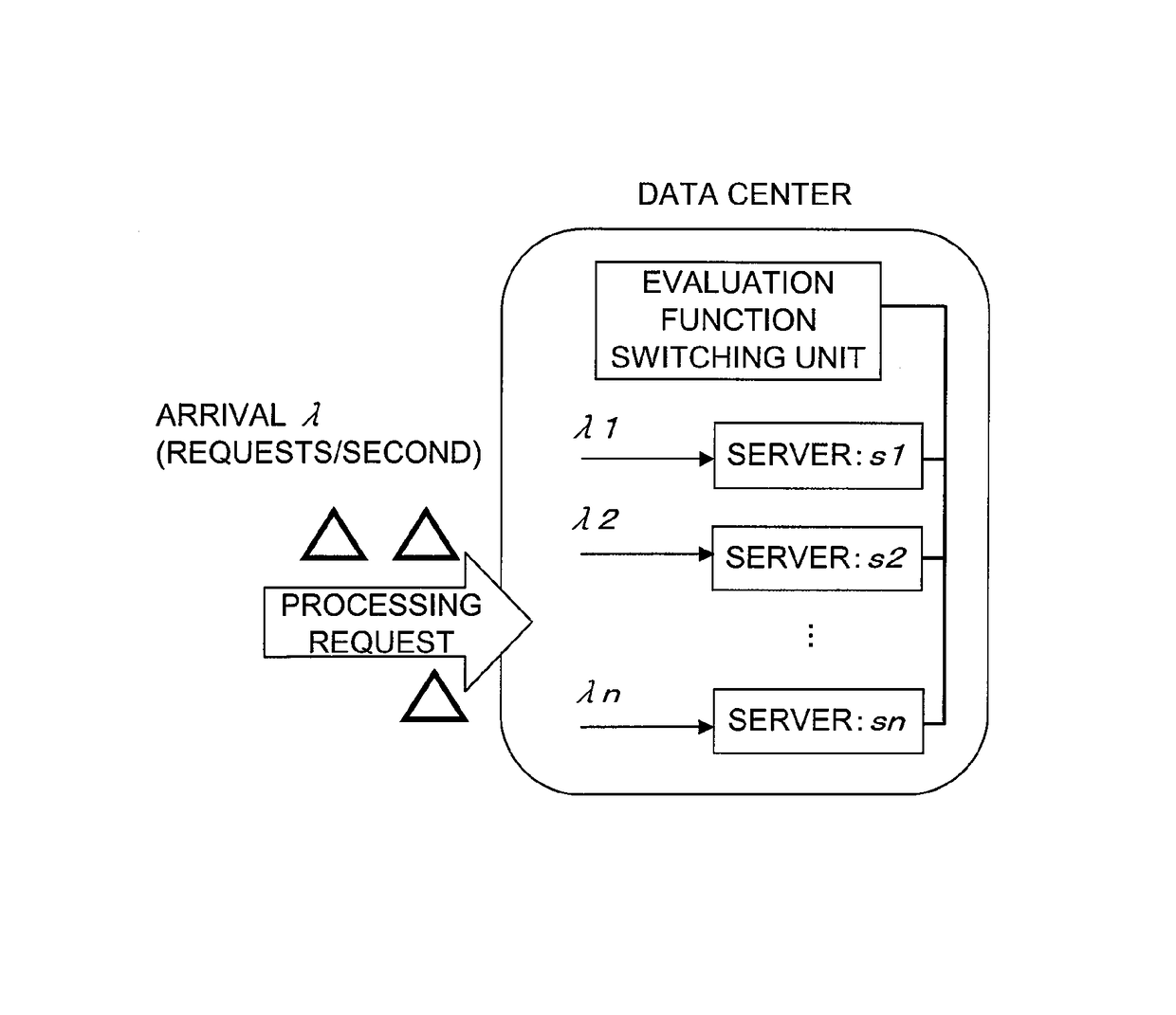
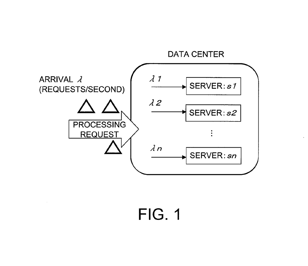
[0114]The invention of this application is carried out for the load balancing among resources of a data center that is illustrated in FIG. 1. The operation level (n represents a function block number) of a resource in this case corresponds to a task amount allocated to the resource.

[0115]When load balancing among resources of a data center is considered, restraint conditions that matter to an administrator are response, throughput, energy, and the like. An embodiment of the invention of this application in which response and throughput are restraint conditions is described first.

[0116]Response and throughput, which have a strong relation to each other, are respectively defined as follows. A response R is the very time required for processing, and a throughput S is a workload processed per unit time. Therefore, simply, the following Expression (10) is established in relation to a requested workload k.

S=λ·R  (10)

[0117](S≦1)

[0118]However, an effective response Re of an actual resource ...

second embodiment

[0132]The invention of this application is carried out for the load balancing among resources of the data center of FIG. 1 as in the first embodiment. The first embodiment is an embodiment of the invention of this application in which response and throughput are restraint conditions. Described here is an embodiment of the invention of this application in which energy is a restraint condition. Using energy as a restraint means that the system is to be run while saving as much electric power as possible.

[0133]This, too, is basically the matter of how to set an evaluation function.

[0134]By referring to a muscle efficiency expression, the energy efficiency of what operates can be expressed as the following Expression (13) with the use of idle power consumption Hdef, working power consumption W(λ), and additional working power consumption (such as power consumption of an air cooling fan) H.

[0135]fi⁡(λ)=W⁡(λ)Hdef+W⁡(λ)+H(13)

[0136]This efficiency is in general a convex function that peaks ...


PUM


Abstract

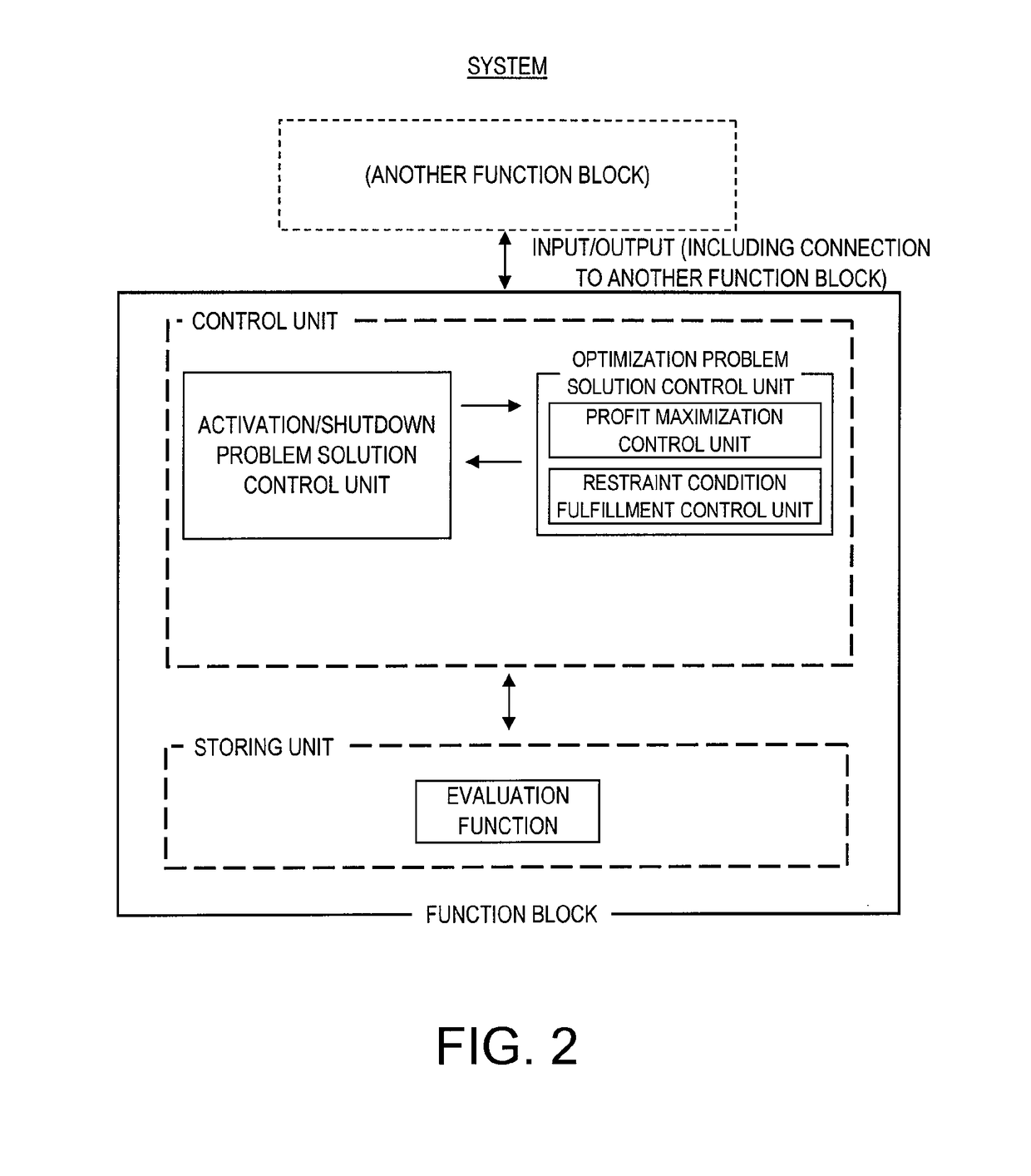
An object is to provide a system in which components can overall operate in concert with one another by using only functions about the components, without using the theory of probability. The system includes a plurality of function blocks correlated to one another. The plurality of function blocks each include: a storing unit including an evaluation function that is associated with its own function block; a profit maximization control unit for adjusting the operation level of its own function block by information about the evaluation function of another of the plurality of function blocks that has a relation with its own function block; an activation / shutdown problem solution control unit for adjusting a suppression of the operation level by profit maximization control based on an active state / shutdown state of its own function block; and a restraint condition fulfillment control unit for adjusting the operation level of its own function block based on a restraint condition that is to be fulfilled by its own function block and all of the plurality of function blocks together.

Description

[0001]This is a National Stage of International Application No. PCT / JP2012 / 061933 filed May 1, 2012, claiming priority based on Japanese Patent Application No. 2011-114266 filed May 23, 2011, the contents of all of which are incorporated herein by reference in their entirety.TECHNICAL FIELD[0002]This invention relates to a system that comprises a plurality of function blocks and that can operate with the function blocks integrated in a manner adaptive to autonomous decentralization.BACKGROUND ART[0003]Currently, an increase in system scale and a phenomenon where what has not been systematized is suddenly turned into a large-scale system are in progress in various fields. A typical example of the former is found in the IT field such as data centers and networks that are related to a technology called cloud, and the scale thereof is increasing year after year. An example of the latter is found in the infrastructure field such as electric power, energy networks, and cities, which are a...

Claims


Application Information

Patent Timeline
Patent Type & Authority Patents(United States)
IPC IPC(8): G06F19/00G06Q10/06G06Q10/04G05B13/02
CPCG05B13/02G06Q10/04G06Q10/06
Inventor OGAWA, MASATSUGUTANAKA, ATSUHIROMATSUDA, YUMAYANO, MASAFUMI
Owner NEC CORP
Learn More