Femto cell devices

a cell device and femto technology, applied in the field of femto cell devices, can solve the problems of inability or not advisable to reserve a 5 mhz carrier for femtos, small available 3g spectrum in which umts technologies are currently deployed, and inability to carry out a backhaul, etc., to achieve the effect of reducing the number of false handover events, reducing the impact on the backhaul requirements of femto

Active Publication Date: 2017-04-25
ALCATEL LUCENT SAS
View PDF15 Cites 2 Cited by
  • Summary
  • Abstract
  • Description
  • Claims
  • Application Information

AI Technical Summary

Benefits of technology

[0017]A femto cell device in accordance with the invention may enable the number of false handover events, with associated wastage of valuable radio resources, to be reduced. Also, impact on the backhaul requirements for femto cells may be reduced compared to previous arrangements as there can be a significant reduction in signaling traffic and potential overhead.
[0018]In a cellular network, handover requires security credentials, uplink scrambling code and the like to be provided to the destination base station. If there are many candidate destinations, due to there being ambiguity in femto identification, the plain text content of the connection can potentially be maliciously retrieved at every cell considered to be a candidate. By identifying authorized user terminals and rejecting femtos as possible candidates when a user terminal is not authorized, the number of candidate cells may be reduced and privacy enhanced.

Problems solved by technology

However, this approach is undesirable as along term solution.
In several territories, especially in some European countries, the available 3G spectrum in which UMTS technologies are currently deployed is very small and is often limited to a single 5 MHz carrier required for UMTS.
Thus, making such a reservation of 5 MHz carrier for UMTS femtos is either impossible or not advisable due to loss of macro-cell capacity.
As air interface standards evolve to wider bands, such as for example, 20 MHz in WiMAX or for LTE (UMTS Long Term Evolution), static allocation becomes more expensive.
This approach is termed “concurrent co-channel reuse” but poses significant challenges, some of which have been addressed in the context of UMTS co-channel femto cells.
One problem with concurrent co-channel reuse is that dense deployments of femto cell devices, for example, thousands of femto cells being deployed per macro-cell, may lead to significant femto-to-macro interference and a consequent reduction in macro-cell capacity and performance.
Another problem arising from dense femto deployment is an associated increase in network signaling, for example, handover and location area updates, and data plane traffic, for example during handover.
As end user handsets are unable to distinguish between femto device base stations and macro base stations, they are also unable to determine which femto cells they are permitted to use and those from which they are excluded.
Accordingly, handsets will attempt to make use of the services provided by any femto and many such attempts fail because of the exclusive access restrictions on femtos.
Significant amounts of unnecessary signaling and data plane traffic are generated by handsets attempting to use excluded femtos and their subsequent denial of service.
This scrambling code is usually not sufficient to uniquely identify the destination femto cell.
This results in a large overhead in femto cell backhaul requirements and in femto cell radio resources.
It is possible that the UE is not permitted to access any of the femtos on the street 1, so all handover attempts in this case are a waste of resources because they will ultimately be denied.

Method used


Image

  • Femto cell devices
  • Femto cell devices
  • Femto cell devices

Examples


Embodiment Construction

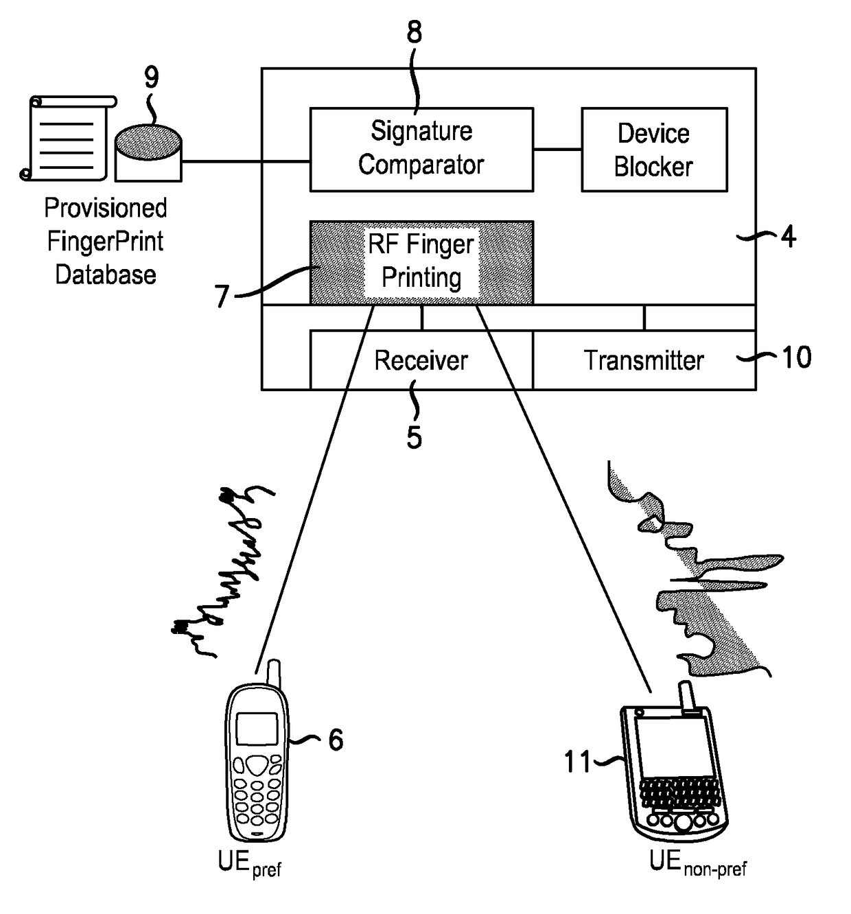
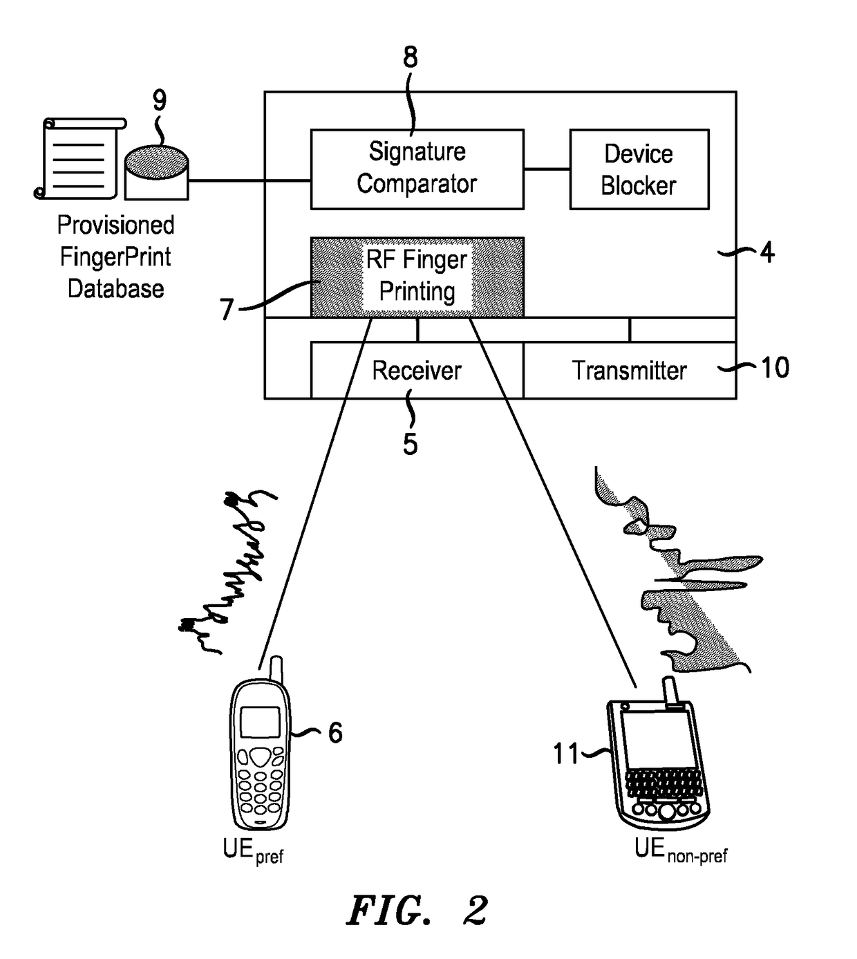
[0027]With reference to FIG. 2, a femto base station 4, also referred to as a femto cell, includes a receiver 5 that detects the transmission of a nearby user terminal (UE) 6 while the UE 6 is in an active call with a macro cellular base station (not shown). An analyzer 7 determines the RF signature imposed on the received UE 6 transmissions. The determined UE RF signature is communicated to an authorizer 8 which includes a comparator for comparing the received RF signature with RF signature data for user terminals held in a store 9. The stored RF signature data is associated with user terminals that are permitted to use the femto cell 4. If the comparator determines that there is a close enough match between the determined RF signature for the UE 6 and a stored signature, the UE is identified as being authorized to use the femto base station 4. The femto base station 4 sends a message via a transmitter 10 to the macro cell base station to inform it that it is a possible handover ca...


PUM


Abstract

A femto cell device comprises: a receiver for receiving transmissions from a user terminal in an active call with a macro cellular network node; an analyzer for determining a radio frequency (RF) signature characterizing the transmissions received from the user terminal; an authorizer arranged to use the RF signature to determine if the user terminal is authorized to use the femto cell device; and a communicator for informing the core network that the femto cell device is a valid candidate handover target for the user terminal when the user terminal is determined by the authorizer to be authorized to use the femto cell device.

Description

FIELD OF THE INVENTION[0001]The present invention relates to femto cell devices.BACKGROUND[0002]In cellular communications networks, femto cell devices, also termed femto cells or simply femtos, are devices with a small coverage area and are typically deployed in homes, enterprise buildings and public places to further enhance macro-cellular services. Femto cell devices provide coverage underlying a macro cell network, for example. In this specification, the terminology femto cell device, femto cell, femto and femto base station are used interchangeably and refer to the device that provides the coverage.[0003]Femto cell devices offer several advantages. As a femto cell coverage area is relatively small compared to that of a macro cell, data rates to end user devices may be substantially higher than those achieved via an overlying macro cell layer. This may provide improved battery life and end-user service experience. In addition, femto cells off-load end users that otherwise would ...

Claims


Application Information

Patent Timeline
Patent Type & Authority Patents(United States)
IPC IPC(8): H04W36/00H04W12/06H04W36/04H04L29/06H04W84/04
CPCH04W12/06H04L63/0876H04W36/04H04W84/045H04W12/79H04W16/26H04W36/34H04W48/02
Inventor CLAUSSEN, HOLGERKENNEDY, IRWIN
Owner ALCATEL LUCENT SAS
Why Eureka
Try Eureka