
Liquid crystal display

a liquid crystal display and liquid crystal technology, applied in non-linear optics, instruments, optics, etc., can solve the problem of lower visibility on the side, achieve the effect of preventing the deterioration of the transmittance preventing the irregular movement of the liquid crystal molecules

Active Publication Date: 2017-05-02
SAMSUNG DISPLAY CO LTD
View PDF15 Cites 0 Cited by
  • Summary
  • Abstract
  • Description
  • Claims
  • Application Information

AI Technical Summary

Benefits of technology

The invention provides a way to prevent deterioration in the display of LCDs that occurs when liquid crystal molecules move irregularly in certain areas. This is achieved by creating cutouts in one of the field generating electrodes and specifically addressing the areas where the cutouts meet. This approach not only prevents deterioration in the transmittance of the LCD but also allows for the creation of two field generating electrodes on one substrate, which is advantageous for some applications. Overall, this invention improves the quality and reliability of LCD displays.

Problems solved by technology

The LCD may have light weight and thin formation thereof are easily obtained while it has a drawback in that side visibility is lower than front visibility, and liquid crystal arrangements and driving methods of various types have been developed to solve the drawback.

Method used


Image

  • Liquid crystal display
  • Liquid crystal display
  • Liquid crystal display

Examples


Embodiment Construction

[0031]The invention will be described more fully hereinafter with reference to the accompanying drawings, in which exemplary embodiments of the invention are shown. As those skilled in the art would realize, the described embodiments may be modified in various different ways, all without departing from the spirit or scope of the invention.

[0032]In the drawings, the thickness of layers, films, panels, regions, etc., are exaggerated for clarity. Like reference numerals designate like elements throughout the specification. It will be understood that when an element such as a layer, film, region, or substrate is referred to as being “on” another element, it can be directly on the other element or intervening elements may also be present. In contrast, when an element is referred to as being “directly on” another element, there are no intervening elements present.

[0033]It will be understood that, although the terms “first,”“second,”“third” etc. may be used herein to describe various eleme...


PUM

PropertyMeasurementUnit
diameteraaaaaaaaaa
diameteraaaaaaaaaa
angleaaaaaaaaaa

Abstract

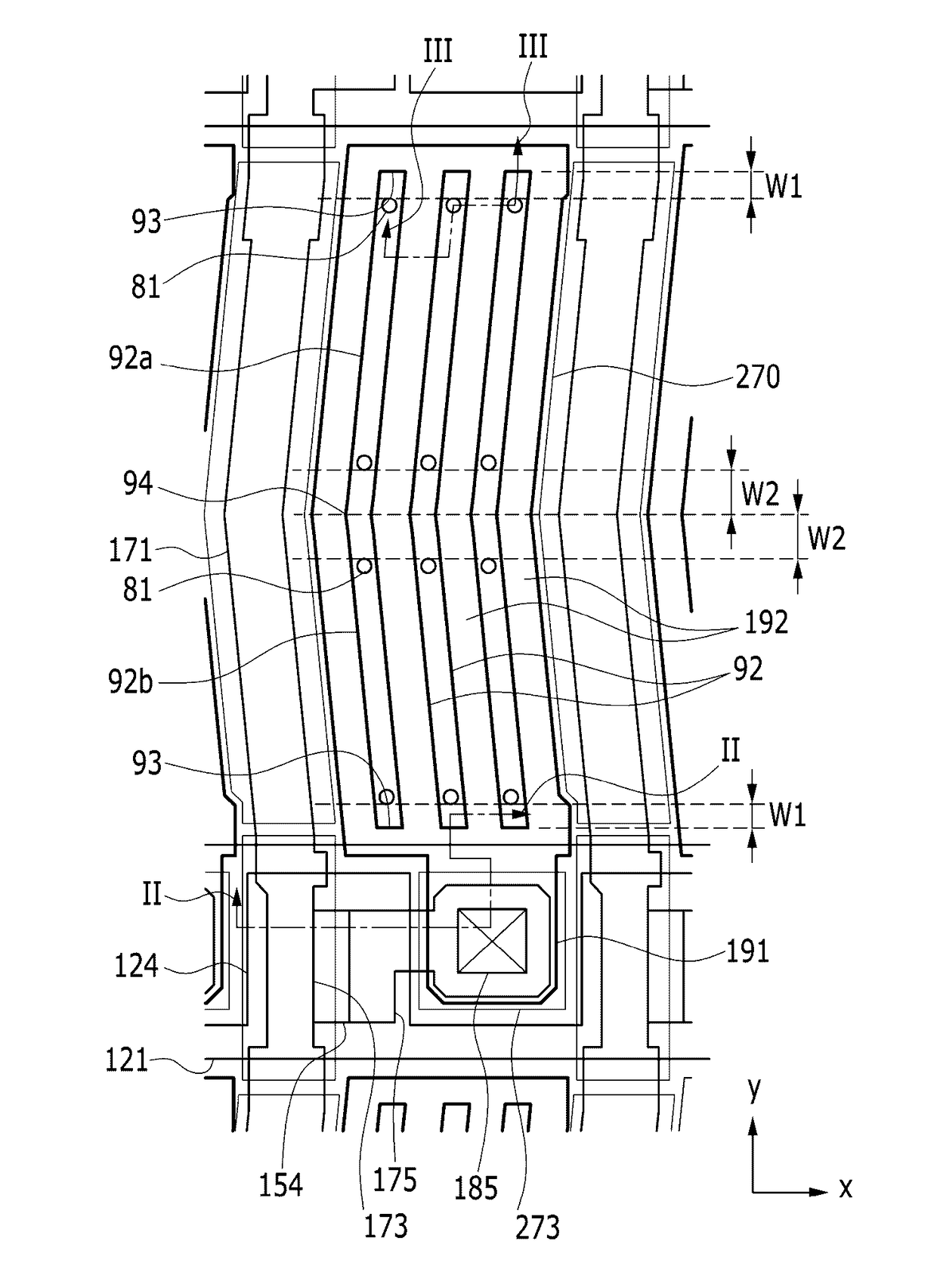
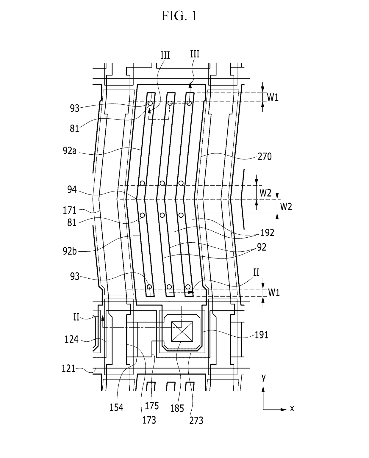
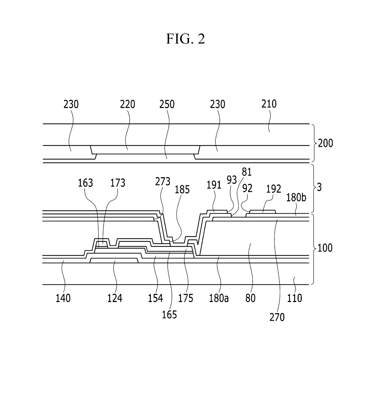
A liquid crystal display according to an exemplary embodiment of the invention includes a substrate, a gate line and a data line disposed on the substrate, a first passivation layer disposed on the gate line and the data line, a first electrode disposed on the first passivation layer, a second passivation layer disposed on the first electrode, and a second electrode disposed on the second passivation layer and including a plurality of first cutouts and a plurality of branch electrodes defined by the plurality of first cutouts, wherein the second passivation layer has a second cutout overlapping a portion of the plurality of first cutouts, and the second cutout is defined close to the end of the first cutout.

Description

[0001]This application claims priority to Korean Patent Application No. 10-2014-0033646 filed on Mar. 21, 2014, and all the benefits accruing therefrom under 35 U.S.C. §119, the entire contents of which are incorporated herein by reference.BACKGROUND[0002](a) Field[0003]The invention relates to a liquid crystal display (“LCD”), and in detail, relates to an LCD without display quality deterioration when increasing transmittance.[0004](b) Description of the Related Art[0005]A liquid crystal display (“LCD”) is one of the most widely used flat panel displays, and displays images by applying voltages to field-generating electrodes to generate an electric field in an LC layer that determines orientations of LC molecules therein to adjust polarization of incident light.[0006]The LCD may have light weight and thin formation thereof are easily obtained while it has a drawback in that side visibility is lower than front visibility, and liquid crystal arrangements and driving methods of variou...

Claims


Application Information

Patent Timeline
Patent Type & Authority Patents(United States)
IPC IPC(8): G02F1/136G02F1/1343G02F1/1337G02F1/1333
CPCG02F1/134363G02F1/13439G02F1/133707G02F1/133345G02F2001/134372G02F1/134372
Inventor PARK, SEUNG HYUNSONG, JUN HO
Owner SAMSUNG DISPLAY CO LTD
Learn More