Base for an electrical lamp that prevents rotation and a more efficient method of assembling a base for an electrical lamp

a technology of electrical lamps and bases, which is applied in the direction of semiconductor devices, lighting and heating devices, lighting support devices, etc., can solve the problem of limiting the efficiency by which the base may be assembled, and achieve the effect of reducing the shortcoming and limiting the efficiency

Active Publication Date: 2017-05-09
KONINK PHILIPS ELECTRONICS NV
View PDF7 Cites 0 Cited by
  • Summary
  • Abstract
  • Description
  • Claims
  • Application Information

AI Technical Summary

Benefits of technology

[0005]It has been realized that there is room for improvement upon the above-described LED lamp designs. More specifically it has been realized that pinching of a housing to an enclosure or a screw-connection between an insulation housing and an electrode cap inter alia may limit the efficiency by which the base may be assembled. It is therefore an object of the present invention to address and at least partly reduce this shortcoming by providing a base which better lends itself for an efficient assembly.

Problems solved by technology

More specifically it has been realized that pinching of a housing to an enclosure or a screw-connection between an insulation housing and an electrode cap inter alia may limit the efficiency by which the base may be assembled.

Method used


Image

  • Base for an electrical lamp that prevents rotation and a more efficient method of assembling a base for an electrical lamp
  • Base for an electrical lamp that prevents rotation and a more efficient method of assembling a base for an electrical lamp
  • Base for an electrical lamp that prevents rotation and a more efficient method of assembling a base for an electrical lamp

Examples


Embodiment Construction

[0037]The present invention will now be described more fully hereinafter with reference to the accompanying drawings, in which currently preferred embodiments of the invention are shown. This invention may, however, be embodied in many different forms and should not be construed as limited to the embodiments set forth herein; rather, these embodiments are provided for thoroughness and completeness, and fully convey the scope of the invention to the skilled person.

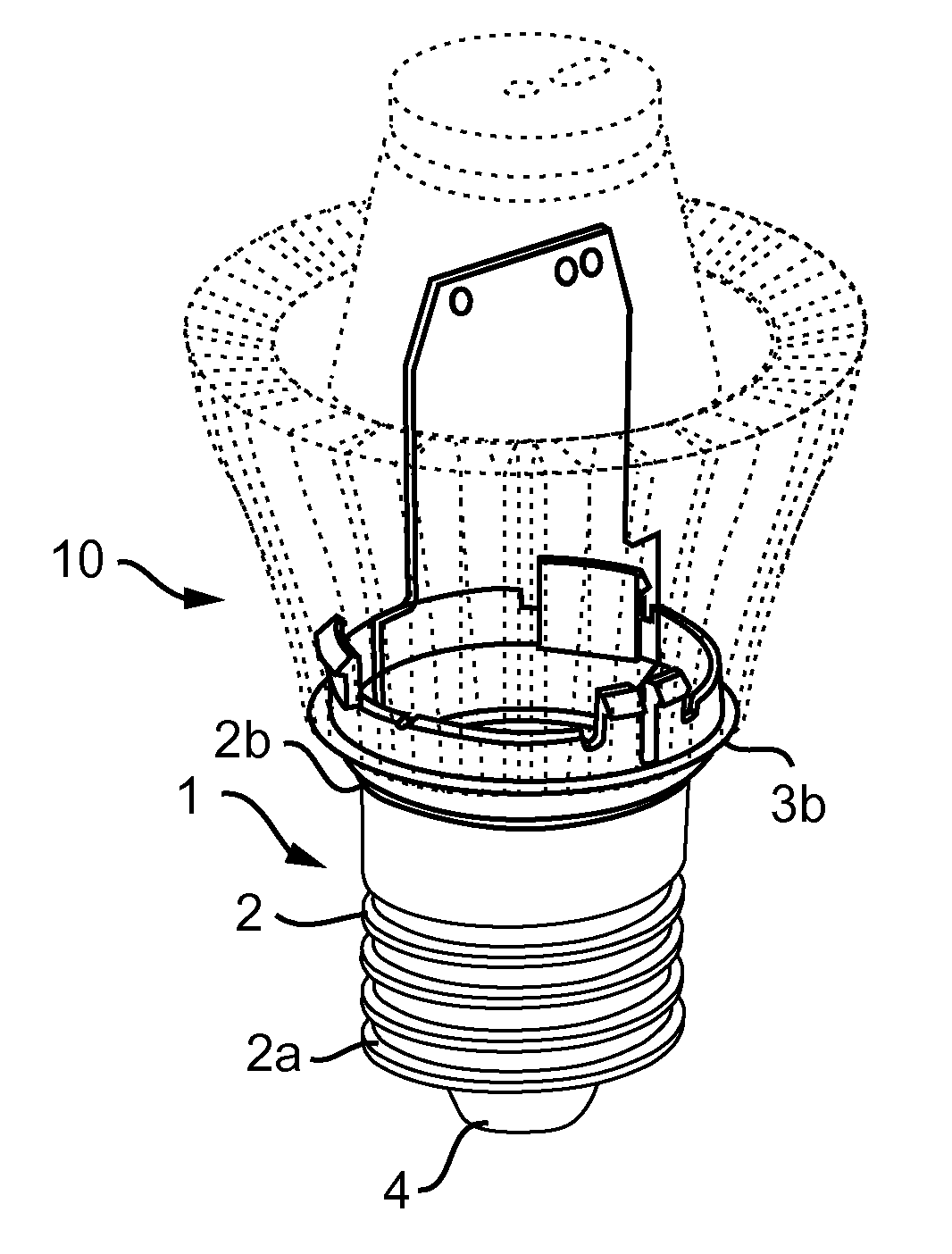
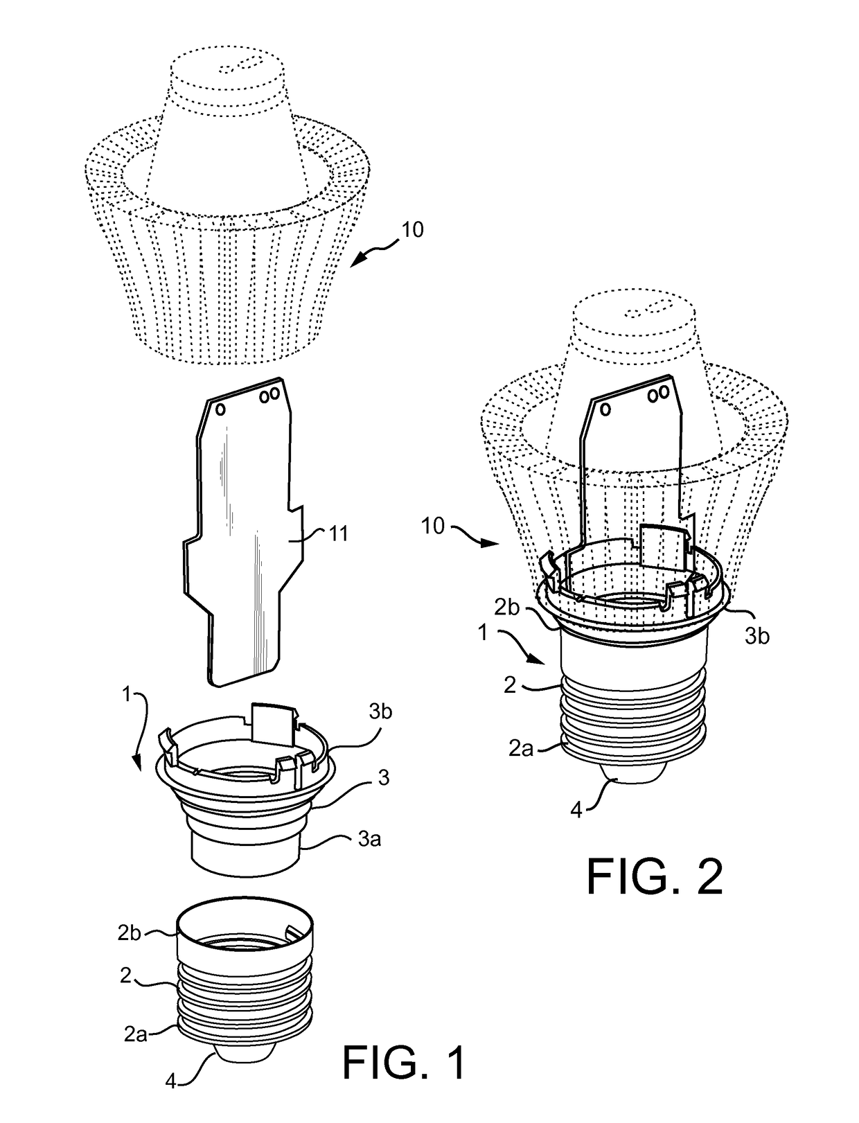
[0038]FIGS. 1 and 2 illustrate a base 1 for an electric lamp in accordance with one embodiment. FIG. 1 illustrates the base 1 in an unassembled condition. FIG. 2 illustrates the base 1 in an assembled condition. The base 1 comprises an electrically conducting tubular enclosure 2. The enclosure 2 is provided with an outer thread. The outer thread enables the base 1 to be screwed into an Edison-type socket. The enclosure 2 extends between a first end portion 2a and a second end portion 2b. This direction of extension may be r...


PUM

PropertyMeasurementUnit
electrically conductingaaaaaaaaaa
energy efficiencyaaaaaaaaaa
axial displacementaaaaaaaaaa

Abstract

According to an aspect there is provided a base for an electric lamp. The base includes a tubular enclosure extending along an axial direction between a first and a second end portion of the enclosure, an insulator attached to the first end portion of the enclosure. The insulator has an inner portion facing towards an inner space of the enclosure, an outer portion facing away from said inner space and at least one channel for receiving a contact pin, the channel extending from the outer portion, through the insulator and leading into said inner space. The base also includes a housing for accommodating electrical circuitry for operating the electric lamp. The housing is attached to the inner portion of the insulator such that a rotation of the housing relative to the insulator about the axial direction is prevented, and a rotation of the housing relative to the enclosure is prevented.

Description

CROSS-REFERENCE TO PRIOR APPLICATIONS[0001]This application is the U.S. National Phase application under 35 U.S.C. §371 of International Application No. PCT / IB13 / 054237, filed on May 22, 2013, which claims the benefit of U.S. Provisional Patent Application No. 61 / 655,548, filed on Jun. 5, 2012. These applications are hereby incorporated by reference herein.FIELD OF THE INVENTION[0002]The present inventive concept relates to a base for an electrical lamp and a method of assembling a base for an electrical lamp.BACKGROUND OF THE INVENTION[0003]The development in the field of light emitting diodes (LEDs) has made it practicable and economical to replace traditional light sources, such as incandescent light lamps or fluorescent lamps, with LED lamps for both indoor and outdoor lighting. Given their favorable energy efficiency and long lifespan LED lamps are often considered more environmentally friendly than their traditional counter parts.[0004]Today, LED lamps are available in various...

Claims


Application Information

Patent Timeline
Patent Type & Authority Patents(United States)
IPC IPC(8): F21K99/00F21V21/00F21K9/23F21K9/90F21V23/00H01J5/54F21Y101/00
CPCF21K9/238F21K9/23F21K9/90F21V21/00F21V23/006H01J5/54F21Y2101/00Y10T29/49002F21K99/00F21Y2115/10
Inventor GIELEN, VINCENT STEFAN DAVID
Owner KONINK PHILIPS ELECTRONICS NV
Why Eureka
Try Eureka